Continue to Site

Welcome to EDAboard.com

Welcome to our site! EDAboard.com is an international Electronics Discussion Forum focused on EDA software, circuits, schematics, books, theory, papers, asic, pld, 8051, DSP, Network, RF, Analog Design, PCB, Service Manuals... and a whole lot more! To participate you need to register. Registration is free. Click here to register now.

Help needed to repair a Sony Trinitron KV-2165MT power failure

Status
Not open for further replies.
Perhaps I forgot to mention that the one I have here is a 60W lamp
Is this a 220 V lamp?

I think let's start near a 40W load. If you only have 220 V lamps, then you may have to parallel some to get enough load on the PSU. If you can get the PSU up to voltage with this, we should be ok. We can then verify with a 60W load.

The PSU will still run under a lighter load, but we need to know that it can handle the rated load the set will require.
 

Yes, it is a 220V lamp!

Unfortunately, it's the only one I've got at the moment. But, if it's very critical to get the PSU up, I can look around for more.

Thanks

- - - Updated - - -

I'm back to the set now. I just started off by removing C606 as suggested by E-design. Not sure if I can measure this HV cap with the meters I've got.

Well, testing the capacitance with my DMM, it reads 4.00 nF. In the resistance test mode (40 MΩ) the meter stays on "OL" and the decimal point doesn't show any movement.

My analog meter has a 12.5V output on the 10KΩ range. When tested with the analog meter on that range, the needle moves slightly, less than 0.5mm, then goes back to 0.

I will try to check a similar ceramic disc cap and see whether the readings are similar, too.
 

Unfortunately, it's the only one I've got at the moment. But, if it's very critical to get the PSU up, I can look around for more.
You can use it for initial testing. If you can get the PSU driving this at full voltage, you can parallel a similar lamp as a final test.

The HV caps can break down under voltage. The only sure way to eliminate them without the right equipment is to replace it with a new one with similar ratings. I have a 0 - 5 kV supply with an adjustable current limit that is ideal to check HV caps for leakage.

I don't know if you checked these before, but make sure the rectifier caps are all good (C609-100 uF/C610-220 uF). If these are leaky, they can certainly put the PSU into current limit mode. It is a good idea to just replace them especially is the set is more than five years old.
 

Hello E-design,

Yes, replacing all the e-caps, at least around the PSU, is the best bet in our situation. I believe the set is more than 10 years old.

Unfortunately, I don't have that kind of equipment, as I do not do repairs very often.

Anyways, the following are the results for last components checked:

C619: 49.40 uF. It's cracked on the bottom, but the reading seems ok.
R604: 11.9 Ω. A portion of its outer coating fell off.
R623: 0.4 Ω
C607: The DMM moves to uF shows "OL". Resistance measures 1.5 kΩ for this cap
C626, 27, and 28 are all ok. They all measure the same, 2.88 nF.

I would like to mention here that I didn't mount anything yet for R620. I don't know if this affects the startup circuit.

Now, the good news is, I managed to get the older set, the KV-2162M9, back to life. It was working for several weeks before it refuses to start up later. The first session, I replaced all the filter caps, but the set started to make loud clicks and never started up. Now, after replacing the 33uF/160V e-cap next to the flyback transformer, and re-solder a dozen of dry joints at the bottom half of the PCB, the set started up and it's still working now. However, after turning the power on, the set has made a very loud clicks then the picture appeared. I thought it's a relay not getting enough drive, but it turns out the clicks were of a high voltage spikes coming from the back of the PCB, more likely around the flyback base, CRT connectors, etc. I didn't open it again, but when looking through the ventilation holes while the set is starting up, I could see several spikes in different directions then the set starts up and the picture appears. Yesterday, the spikes were coming out every now and then even when the set is working normally, but today they were gone once the set is working normally.

One more thing, I noticed that the picture was a little bit distorted, especially for lines and subtitles, where they appear curvy and they leave a transparent shadow as they move around the screen. All in all, its picture is still acceptable, but I will try to open it again to see whether I can do something, adjust something, perhaps I can improve the picture.

I remember that I played with the "focus" knob on the flyback transformer, but I suppose I returned it back to where it was initially. Maybe I need to do this while the set is live?

One more thing to add is, I was wrong on my assumption regarding the red LED. It looks like, the LED turns off when the set starts up normally and only keeps on while the set is in the standby mode. Now, sometimes the set refuses to work and it enters the standby mode immediately after turning the power on. By then, I have to press and hold my finger on one of the Channel +/- buttons on the front panel, the set starts to make certain high-voltages spikes for almost 2~3 seconds, then it starts up again.

This CRT thing is really frightening me and sometimes I kinda feel it's gonna explode into thousand pieces and kill everyone in the room! :))

Thanks again,

e-music
 

C607: The DMM moves to uF shows "OL". Resistance measures 1.5 kΩ for this cap
Not good. Replace.

I would like to mention here that I didn't mount anything yet for R620. I don't know if this affects the startup circuit.
Should not affect the start.

make sure the rectifier caps are all good (C609-100 uF/C610-220 uF)
This checked ok?

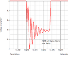
Another cap that is very important is C608, as this controls the ringing on the anode (between leakage inductance of winding 11/12 and diode capacitance) and prevents a reverse breakdown of the D604. Below is an example of the ringing possible with an open C608.
 

Attachments

  • snub.png
    snub.png
    16.9 KB · Views: 133

Hello e-music,
I would recommend that you replace C607 (0.330uF/330nF), as suggested by E-design. I'm not sure what C607 looks
like physically, but make sure its rated at least 400 or 630 volts.
I would also like to suggest replacing C619 (47uF 16V), with a low ESR type as well. This wouldn't cost much at all.

Did you get a chance to measure R603 (68Ω 3W) to see if its gone high or open circuit?

ANY parts you find that have been cracked, overheated or damaged, should be replaced regardless if they measure OK.
Since you've had a major overload in the power supply, many components had their full ratings tested. Hence the
cracks, overheated etc. This doesn't mean that all parts should be replaced in the PSU, but only the ones that have
physically shown signs of distress.
There is a good possibility that later down the line these parts may eventually fail.

As E-design has mentioned:

and just easier to eliminate them as suspects by replacing them with a new correctly rated part

Regards,
Relayer
 

I would recommend that you replace C607 (0.330uF/330nF), as suggested by E-design. I'm not sure what C607 looks
like physically, but make sure its rated at least 400 or 630 volts.

I suspect it would be a pulse-rated capacitor, something like the WIMA MKP series.
 

No, I didn't check C609-100 uF/C610-220 uF yet, but I plan to test/replace them all in one shot, as soon as I get the new caps. This also applies to C607.

So, I will get back to here once those caps are checked/replaced and will report the results by then.


Thank you again for your help!

- - - Updated - - -

@ Relayer:

Hello Relayer,

Thank you again for getting back here. I didn't check R603 yet, I will check it and let you know as soon as I get to the set again.

Well, since the majority of sensitive parts are already replaced in the PSU, I believe it's a good idea to replace the caps, too.

I will place an order for some caps, resistors, and will let you know as soon as they are replaced!

Anyways, I expected to hear something from someone of you guys about those sparks underneath.

Thanks again
 

Hello e-music,

Anyways, I expected to hear something from someone of you guys about those sparks underneath.

By the description of the sets symptoms you mentioned in an earlier post, it does seem the arching is coming
from the flyback transformer.
Best way to see exactly where the arching is occurring, is to remove the back cover on the telly and grabbing an
old blanket, then covering yourself and the rear of the TV so its totally dark. Then get someone to switch the TV on,
while observing the sparks. Don't put your face too close to any of the boards.
Also, have a look at the ultor cap to see if there are any minute sparks being generated between the cap lip and
the picture tube. What ever you do, DON'T touch the cap while the TV is on.
As you've already surmised, the FBT and the spark-gaps on the CRT PCB should get your main attention.

By the way, when you do hear the arching, is the picture affected in any way? Interference, which may be minor,
but should be noticeable.

Please let us know what you observe.
Regards,
Relayer
 

Hello Relayer,

Thank you very much for your input.

when you do hear the arching, is the picture affected in any way? Interference, which may be minor,
but should be noticeable.

Yes, I have observed some interferences during the clicks/sparks, but they were hardly noticable.

Of course, I will have to remove the cover again and look at it in dark condition and see where those sparks are originating from.

I will report the results as soon as I'm done.

Thank you again!
 

Hello again,

Today I turned the set on, the picture was all in blue. No colors at all. I opened the set to take a look inside so I can find where the sparks are coming from, and to my astonishment, I found that I made a very big and stupid mistake right there. Well, the cable for the degaussing circuit was not connected to the CRT board and was left floating above the main board. The spark was coming from the connector while it was close to an exposed component, more likely a resistor.

I have connected the cable to the CRT board, and now the set starts up normally, but only shows a grey/blue picture.

I hope I didn't damage the CRT tube, color transistors, or anything else.
 

Just a small correction, it seems it's a black and white picture, not a blue one.

Still waiting for the caps for the newer set in order to complete the checks with the light bulb load.
 

Hello e-music,

I hope I didn't damage the CRT tube, color transistors, or anything else

No. Doubtful any of the components on the CRT board have been damaged, as the loss
of color has to be common to all three tube guns, as well as the RGB transistors.

It seems more likely that IC301 or IC401 are affected. Either the IC/s are faulty themselves
or the support component/s are at fault.

Please see the picture below:

https://imgur.com/Uyq0MD7

As you can see the areas marked with the RED circles on IC301,
I need you to check those voltages, and compare them with those marked on the diagram.
As for the the RED and GREEN circles on IC401, please measure them and compare the readings
with those marked in the box to the right.

If you're getting the same voltages regarding the GREEN shaded areas,
then it would be stuck in SECAM mode.
Unfortunately it could even be stuck in NTSC mode, but there's no discrimination in voltage readings,
but I'm doubting it. Though I need to make sure that IC401 isn't faulty.
The fault will more than likely either be in IC301 or its support circuitry.

Its a pity you don't have an oscilloscope and a color pattern generator, as they would help immensely
in diagnosing the fault. But we'll have to make do, though it may get a tad laborious.

Please let us know how you get on.
Regards,
Relayer
 

Hello guys,

I'm trying to order some components for the new set, but have no idea what PN might fit C607 (0.33uF).

This is how the cap looks like:

C607_CAP.JPG

Thanks in advance!
 

Attachments

  • C607_CAP.jpg
    C607_CAP.jpg
    398.3 KB · Views: 160

Hello e-music,

I'm trying to order some components for the new set, but have no idea what PN might fit C607 (0.33uF)

Did you get a chance to measure R603 (68Ω 3W), or will you be waiting for the caps to arrive first?

Please follow E-design's recommendation for the Metallized Poly Film caps, but be wary of the pitch
spacing on the original, as well as having the cap rated to at least 630V DC to be on the safe side.

Regards,
Relayer
 

You need a capacitor that is rated for pulse applications.
@E-design: Thank you very much. Yes, I will look that up and see how to order it!


@Relayer: Thanks for your reply. Yes, I believe I did, but not quite sure. I will probably do it again once the caps arrive here .
 

Hello again guys!

This is the only series I found available from my supplier for C607. Datasheet attached. Let me know what do you think.

Thank you again!
 

Attachments

  • C607_Candidate.pdf
    96.5 KB · Views: 96

That would be a suitable replacement.
 

Status
Not open for further replies.

Similar threads

Part and Inventory Search

Welcome to EDABoard.com

Sponsor

Back
Top