Continue to Site

Welcome to EDAboard.com

Welcome to our site! EDAboard.com is an international Electronics Discussion Forum focused on EDA software, circuits, schematics, books, theory, papers, asic, pld, 8051, DSP, Network, RF, Analog Design, PCB, Service Manuals... and a whole lot more! To participate you need to register. Registration is free. Click here to register now.

[PIC] Expanding input ports with 74HC165 and output with 74hc595

Status
Not open for further replies.

memo-afeef-nasser

Junior Member level 1
Joined
Jan 20, 2018
Messages
17
Helped
0
Reputation
0
Reaction score
0
Trophy points
1
Activity points
150
Hi everybody
I need to expand input ports with 74HC165 and output ports with 74hc595 on my 18F4550. I'm using shift register 74HC165 and 74hc595
I want to know how to write sample code for reading inputs. Also i would like to know some schematics how to connect shift register to 18F4550. I am working in mikro c for pic FYmWdNi - Imgur.png
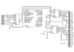
and there is the schematic diagram.
please help me
 

Hi,

A frequently asked question.
Therefore there are a lot if solutions available.
Even in the box below "similar threads" you will find good information.

Do you need us to do the internet research for you?

What have you done so far? What internet examples did you try? And what were the results?

Klaus
 

this simple code at this website
https://forum.mikroe.com/viewtopic.php?f=88&t=45741
and there is the code

Code C - [expand]
1
2
3
4
5
6
7
8
9
10
11
12
13
14
15
16
17
18
19
20
21
22
23
24
25
26
27
28
29
30
31
32
33
34
35
36
37
38
39
40
41
42
43
44
45
46
47
48
49
50
51
52
53
54
55
56
57
58
59
60
61
62
63
64
65
66
67
68
69
70
71
72
73
74
75
//////////////////////////////////////////////////////////////////////////////
// READING 74HC165 AND WRITING 74HC595 SHIFT REGISTERS WITH PIC18F4550
//////////////////////////////////////////////////////////////////////////////
 
//////////////////////////////////////////////////////////////////////////////
// NUMBER OF 74HC165s IN YOUR CIRCUIT (change to whatever you want)
//////////////////////////////////////////////////////////////////////////////
const int number_of_74hc165s =1;
 
#define latch_pin LATA.F5 // 74HC165 PIN #1
#define clock_pin LATA.F4 // 74HC165 PIN #2
#define data_pin PORTA.F3 // 74HC165 PIN #9
 
#define shift_register PORTA.F2 // 74HC595 PIN #11
#define storage_register PORTA.F1 // 74HC595 PIN #12
#define serial_data PORTA.F0 // 74HC595 PIN #14
 
unsigned char buttons[number_of_74hc165s * 8];
 
void write_outputs_595(char* value) {
unsigned int i = 0;
 
while(i < 8) {
if(value[i] == '1')
serial_data = 1;
else
serial_data = 0;
 
shift_register = 1;
shift_register = 0;
i++;
}
storage_register = 1;
storage_register = 0;
}
 
void read_inputs_165(int number_of_shift_registers) {
unsigned int m = 0;
 
latch_pin = 0;
latch_pin = 1;
 
while(m < number_of_shift_registers * 8) {
clock_pin = 0;
if(data_pin) buttons[m] = '0'; else buttons[m] = '1';
clock_pin = 1;
m++;
}
}
 
void main() {
ADCON1 |= 0x0F;
CMCON |= 7;
 
TRISA = 0x00; // define all ports as outputs
TRISA.F3 = 1 ; // data_pin of 74HC165 must be defined as input
PORTA = 0x00; // clear PORTA
 
while(1) {
// Example how to use 74HC595. First four ports has HIGH value and last four has LOW value
write_outputs_595("010101010");
// Example how to read inputs from shift register 74HC165
read_inputs_165(number_of_74hc165s);
 
// Check Button 1
if(buttons[0] == '1') { write_outputs_595("00000001");delay_ms(2000); }
if(buttons[1] == '1') { write_outputs_595("00000010");delay_ms(2000);}
if(buttons[3] == '1') { write_outputs_595("00000100");delay_ms(2000);}
..............
 
// Button 1 is pressed .....
// Do whatever you want ..
 
}
}


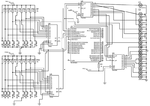
thiscode has work well for one shift reg (74hc164) and one shift reg(74hc595)
but when I uesd it with two shift reg (74hc164) and two shift reg(74hc595)
it didnt work in spite of I change the//// const int number_of_74hc165s =2 ///
what is the wrong?
mZdGPw9 - Imgur.png
 
Last edited by a moderator:

The schematic looks right at first sight, the read part is supposed to work with m=2, you however don't show code for accessing multiple output registers.

In any case, if you don't see what's wrong, check the code execution in real hardware by single-stepping with a debugger.
 

Ihave made some project like so look here **broken link removed**
 

I NOTICED that the16 buttons(inputs) have work well with (74hc165)
but the outputs (the leds) by (74hc595 ) only one shift reg (74hc595 ) has work well
but the another 74hc595 didnot work
only 8 leds have work well
what is the problem?
 

Status
Not open for further replies.

Similar threads

Part and Inventory Search

Welcome to EDABoard.com

Sponsor

Back
Top