rbl671
Newbie level 2
I have a new Carrier Infinity 5 stage heat pump system - best there is. Turns out in their wisdom they will not let the AC function below stage 2 if it is between 60 and 55° and at less than stage 4 if it is between 55 and 40° outside temps. This totally makes this system unusable in my new home that has 4 zones one of which is interior and requires cooling. Unfortunately it took me 2 months to figure this out as it is an "unpublished specification" that is inconsistent with their published specification.
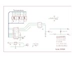
So I now need to "trick" the control board so it is never between these two temperatures. I have a circuit that I want to switch in a parallel resistor (R5) to the outside temperature thermistor (R4) with a small FET (Q1) so it stays about the 60° range. This will allow the unit to run as it should and it does indeed work well when it does.
I am not a circuit guru and even less in code but I built a thermometer a while back and dug all that up. All I need to do is switch in this resistor (I think) and I would like to do it with a small signal N channel FET. I would like to stay away from a relay if this will work and use the old thermometer board with the modification and some additional code that I will post later if this will work electrically. I also don't have any relays. There is no power on the circuit and the HP simply reads the thermistor value and uses a look-up I assume for the corresponding temperature vs. resistance.
Please have a look and give your advice. The display and 7219 work correctly now.
Thanks very much
