Continue to Site

Welcome to EDAboard.com

Welcome to our site! EDAboard.com is an international Electronics Discussion Forum focused on EDA software, circuits, schematics, books, theory, papers, asic, pld, 8051, DSP, Network, RF, Analog Design, PCB, Service Manuals... and a whole lot more! To participate you need to register. Registration is free. Click here to register now.

Boost converter large inductor current spike

Status
Not open for further replies.

shyhwei1

Newbie level 3
Joined
Jan 18, 2018
Messages
3
Helped
0
Reputation
0
Reaction score
0
Trophy points
1
Activity points
24
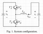
Hi everyone, recently I've been testing an one-leg DC-DC converter operating at boost mode.
???.png
A 400 ohms resistor is attached at vh side. TA-, DA+ are the working elements. The gate of TA+ is well shorted.

Here are the specs:
D =0.33
Input: 48V with a 330uF capacitor
Output: 144V with a 470uF capacitor
Switching frequency: 30kHz
Inductor: 2.007mH
Mitsubishi CM200DY-12NF IGBT module

As I measure the inductor current there appears to be large spikes as the switch turns ON and OFF.
IMG_20180118_114910.jpg
I've change the inductor but no success. Any suggestions?

Note: Current probe Scale is 2A/div
 
Last edited:

Looks pretty much like a measuring artifact. How do you measure current?

Thanks for the reply, I'm measuring with a Tektronix A622 current probe and a YOKOGAWA DL1520 oscilloscope. I've change both of them and using a LeCroy 44Xs oscilloscope, still the same.
IMG_20180118_172316.jpg
 

Looks pretty much like a measuring artifact. How do you measure current?

- - - Updated - - -

Please also clarify the current waveform scale.

- - - Updated - - -

You missed to tell the current scale.

I guess 1A/div in the latest waveform?

I see essentially two explanations
- the current probe exposes a large capacitive voltage cross talk. Do you see differences when attaching it at the hot or cold side of the inductor?
- the inductor has an unusual large parallel capacitance of several nF.
 

I guess the hot and cold side resembles the output and input node of the inductor respectively? If so, I've measured the current at both side, they all have the same issue.
I think I'll try to use an input capacitor with a larger capacitance, or I'll try to connect this inductor to other converters in the lab to check if it's the problem.
 

Measure the inductor parallel capacitance (via self resonance frequency) and check if it corresponds to the observed spikes.

Unfortunately we still don't know how "large" current spikes are.
 

It's not really a boost converter is it....! unless you are running it from right to left...! The volt rise you might get ( left to right) is a resonant phenomenon not a true boost action, if you are using TA+... please study your intended circuit a bit more....

- - - Updated - - -

If running from right to left then:

the diode DA+ will give you large current spikes in the lower fet is you turn the fet on fast - a the diodes in the mosfets you are using are quite slow to reverse recover...
 

Status
Not open for further replies.

Similar threads

Part and Inventory Search

Welcome to EDABoard.com

Sponsor

Back
Top