Continue to Site

Welcome to EDAboard.com

Welcome to our site! EDAboard.com is an international Electronics Discussion Forum focused on EDA software, circuits, schematics, books, theory, papers, asic, pld, 8051, DSP, Network, RF, Analog Design, PCB, Service Manuals... and a whole lot more! To participate you need to register. Registration is free. Click here to register now.

Arduino DC-DC Boost Converter

Status
Not open for further replies.

ebaketa

Newbie level 4
Joined
Oct 19, 2009
Messages
6
Helped
0
Reputation
0
Reaction score
0
Trophy points
1,281
Location
Vukovar
Activity points
1,318
Hello everyone, if someone is willing to help and know, please.

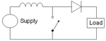
So this is a boost converter, I control it Arduino, I speeded up Arduino PWM at 62kHz and ok when it raises voltage from 5V to 12V, I connect a car light, 12V / 21W, that my converter pushes around 11.8V and 1.7A, the flare glows super.

So then I try with a smaller input voltage of 3.3V and can not get more than 300mA.

Now my question is whether anybody knows how to choose a coil, how much inductance is needed, whether inductance depends on PWM frequency, I think it goes this way but I'm not sure, the higher the frequency to the lower inductance.

If someone has experience or knows, please help!
 

Attachments

  • Boost_circuit_2.png
    Boost_circuit_2.png
    4.5 KB · Views: 110

Last edited:
Thank you for link, I'm gonna try it.

On one another fourm they gave me this link:

**broken link removed**

I belive it's useful.
 

So then I try with a smaller input voltage of 3.3V and can not get more than 300mA.

This is asking a lot of a boost converter. You need to have several Amperes going through your coil. And you cannot have more than 1/10 ohm of total parasitic resistance.

In the second half of the cycle, the supply V is added to whatever comes through the coil.
When the supply is 5V, then it adds 5V. Therefore your coil needs to make up 7V (because you want 12V output).
Now reduce the supply, to 3.3V, and only 3.3V is added to whatever comes through the coil. Therefore the coil needs to make up 9V. It requires substantially more Amperes. Peak current needs to be upwards of 8-10 A.

As an alternate, consider interleaving two or more boost converters. Or, try a flyback converter.
 
Here are your two cases side by side. As you lower the input voltage the peak current that you need to switch will increase with the lower inductor value.
 

Attachments

  • boost.png
    boost.png
    28.8 KB · Views: 230
I'm aware that I need more amps, this is a learning project. Thanks for the reply, it opens my eyes.

- - - Updated - - -

Thank you, this is gona help me to understand, what is happening.

- - - Updated - - -

"E-design"

Looking at these graphs you sent me, I use a coil of 30 uH and that's why 5V works without a fault. How did you calculate on the graph that the coil value of 28.3 uH?
 

The 28.3 uH is just a theoretical recommended minimum value from the requirements you supplied. You can come up with different calculated values depending on your choice of inductor ripple current.
 

Thank you all for help, I managed to raise the voltage to 12V and current to about 600mA, for some more current I need better battery. The one I use now is from the Samsung Galaxy Tab II 7 ", and I'm happy with the result.

Once again thank you all for help!
 

Hi,

I need better battery. The one I use now is from the Samsung Galaxy Tab II 7
Batteries are not good for high frequency switching, therefore you need good capacitors in parallel to the battery.
They need to take the current pulses....an should be located close to the switching devices.

Klaus
 

Status
Not open for further replies.

Part and Inventory Search

Welcome to EDABoard.com

Sponsor

Back
Top