Continue to Site

Welcome to EDAboard.com

Welcome to our site! EDAboard.com is an international Electronics Discussion Forum focused on EDA software, circuits, schematics, books, theory, papers, asic, pld, 8051, DSP, Network, RF, Analog Design, PCB, Service Manuals... and a whole lot more! To participate you need to register. Registration is free. Click here to register now.

schottky diode input protection

Status
Not open for further replies.

brownt

Member level 3
Joined
Sep 25, 2017
Messages
63
Helped
0
Reputation
0
Reaction score
0
Trophy points
6
Activity points
597
Hi,

I am using a pair of schottky diodes to protect the input lines to a digital potentiometer.
The digital potentiometer is powered by the same 5volt line as the microcontroller that drives it via SPI, and the same 5volt line as the schottky diodes.

There is a small voltage at the anode/cathode junction about 50mV when I use BAT54S, and about 150mv when I use 1N5817.

I wonder why that is so, and how to stop it from happening.

thanks input protection.png
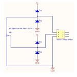
 

In which situation do you measure the said voltage? (Driving current into the diode, open circuit, etc.)

The diodes may be able to slightly increase the ESD strength, they are useless against low impedance voltage sources. Without additional circuit means, there's also a risk of pulling the 5V node high.
 

Hi,

The specified leakage current of BAT54 diodes is max 2uA.
In your case it should be less.

Multiplying 2uA with 50kOhms gives 100mV.

Although this is less than your measured value...I assume the measured value isn't caused by the diodes only.
I assume there are other causes....
* Stressed diode (overtemperature, ESD...)
* leakage current on your PCB
* leakage currents caused by flux residuals --> clean the PCB
* measurement errors

Klaus
 

In which situation do you measure the said voltage? (Driving current into the diode, open circuit, etc.)

The diodes may be able to slightly increase the ESD strength, they are useless against low impedance voltage sources. Without additional circuit means, there's also a risk of pulling the 5V node high.

Measuring in the state shown by the circuit. When the circuit is in its functioning state, the socket is connected to a 5v DC source. I wanted to protect against an overvoltage there, as someone may connect perhaps 10 volts for example. But would the diodes have no effect in that case?
 

The stop-diodes are going to steer current, but in
the 5V-supply-involved loops there has to be a
return leg. This may be assumed to be the "5V"
node/rail but this assumption can be invalid - say,
if the 5V power supply is not there or is instead the
source of the threat, or the 5V supply lacks sink
capability (often the case with local regulators
and even full size "box" supplies in my experience).

Schottky diodes can be "brittle" as they are not meant
to go into breakdown. You need a single pulse
avalanche I*t rating that accommodates whatever
you define the bounding threat waveform (V, I, Z)
to be.

A single ground returned zener (say, 6.2V) on the
wiper might do as well, and need nothing from the
5V supply. Or maybe a boosted zener (5.1V zener
drives NPN base against a sensible shunt B-E) to
get more current capacity than a zener can handle.

For diodes to survive reverse overvoltage there
needs to be a limiting resistance. Where that is
best put, to protect effectively without compromising
accuracy / leakage / whatever, is a trades exercise
following from a better definition of the threat-space.
You call out one possibility (10V connected somehow
to some point) but of course any exposed conductor
is fair game for any present voltage (current loop). Just
what -is- present, possible, credible is always an up
front challenge to protection network design, and the
completeness of this understanding is key to the end
effectiveness "against the world".
 

I think maybe I have not done this correctly. What I wanted to do was prevent greater than 5 volts being applied across the potentiometer, because the digital pot datasheet says that if the voltage across it is more than its VCC, then damage will occur.

But this dual diode I have implemented seems to prevent excessive voltage as in ESD, much like the IC probably already has built in. Is what I need then perhaps just some 5v zener diodes?
 

I think I'd go with the boosted zener - unless you have a
higher voltage supply in which case I'd think about using
a 78L05 little regulator to make the 5V out on the dongle,
able to buck up to about 40V.
 

Hi,

Some devices need to protect overvoltages referred to VCC:
* example: "HC" type logic ICs.
* don't apply input voltages greater than VCC voltage. If VCC = 0V, then don't apply voltages higher than 0.5V..
* --> use schottky diodes

Some devices need to protect overvoltages referred to GND:
* example: "AHC" type logic ICs.
* don't apply input voltages greater than 7V voltage. If VCC = 0V, then you may continously apply voltages of 5V without problems..
* use zener or schottky diodes as you like

The problem with 5.1V zeners are:
* they are unprecise. 10% rated zeners may reach zener current with 4.6V ...or 5.6V
* they start to be conductive from about 2.5V
* the V-I graph isn't very steep. A 100mA current may easily result in voltages higher than 10V. And ESD pulses usually are much higher than 100mA.
I doubt they are good protection circuits. Although they are better than nothing...

I recommend to use dedicated signal line protection circuits. Similar devices than IP4220. Read through it's datasheet.
There are many types ... many will fit your needs.

Klaus
 

Status
Not open for further replies.

Similar threads

Part and Inventory Search

Welcome to EDABoard.com

Sponsor

Back
Top