mshh
Full Member level 6
Code:
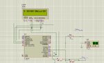
this code for digital clock using codevision atmega 8 simulated on Proteus and it work, when i implement it on atmega 8 chip the lcd displays zero and doesn't count. i set (s) seconds 12 , (m)minutes=2 , (hh) hours=2,(dd) days =4 for fast simulation.
/*****************************************************
Project :
Date : 19/06/2017
Author : mado
chip type : ATmega8
Program type : Application
AVR Core Clock frequency: 8.000000 MHz
Memory model : Small
External RAM size : 0
Data Stack size : 256
*****************************************************/
#include <mega8.h>
#include <stdint.h>
#include <stdio.h>
#include <delay.h>
#include <stdlib.h>
#define ADC_VREF_TYPE 0x00
char str[16]; //allocate on lcd
///time
char s=0,m=0,hh=0,dd=0;// s seconds, m minutes , hh hour, dd day
unsigned char a,b;
#asm
.equ __lcd_port=0x12 //PORTD RS,RW,E
#endasm
// Alphanumeric LCD Module functions
#include <alcd.h>
// Read the AD conversion result
// Timer 2 output compare interrupt service routine
interrupt [TIM2_COMP] void timer2_comp_isr(void)
{
// Place your code here
s=s+1;
if (s==12)
{
s=0;
m=m+1;
if (m==2)
{
m=0;
hh=hh+1;
if (hh==2)
{
hh=0;
dd=dd+4.0833333333333333; // 0.0833333333333333=2/24
}
}
}
}
void main(void)
{
PORTB=0x00;
DDRB=0xFF;
PORTC=0x00;
DDRC=0x00; //port c as input
PORTD=0x00;
DDRD=0xFF; //output
TCCR0=0x00;
TCNT0=0x00;
TCCR1A=0x00;
TCCR1B=0x00;
TCNT1H=0x00;
TCNT1L=0x00;
ICR1H=0x00;
ICR1L=0x00;
OCR1AH=0x00;
OCR1AL=0x00;
OCR1BH=0x00;
OCR1BL=0x00;
// Timer/Counter 2 initialization
// Clock source: TOSC1 pin
// Clock value: PCK2/1024
// Mode: CTC top=OCR2
// OC2 output: Disconnected
ASSR=0x08;
TCCR2=0x0F;
TCNT2=0x00;
OCR2=0x20;
GICR|=0xC0;
MCUCR=0x00;
GIFR=0xC0;
// Timer(s)/Counter(s) Interrupt(s) initialization
TIMSK=0x80;// set timer
// USART initialization
// USART disabled
UCSRB=0x00;
// Analog Comparator initialization
// Analog Comparator: Off
// Analog Comparator Input Capture by Timer/Counter 1: Off
ACSR=0x80;
SFIOR=0x00;
// SPI initialization
// SPI disabled
SPCR=0x00;
// TWI initialization
// TWI disabled
TWCR=0x00;
//////////////
// ADC initialization
// ADC Clock frequency: 1000.000 kHz
// ADC Voltage Reference: AREF pin
ADMUX=ADC_VREF_TYPE & 0xff;
ADCSRA=0x83;
////////////////////
// Alphanumeric LCD initialization
// Connections are specified in the
// Project|Configure|C Compiler|Libraries|Alphanumeric LCD menu:
// RS - PORTD Bit 5
// RD - PORTD Bit 6
// EN - PORTD Bit 7
// D4 - PORTB Bit 2
// D5 - PORTB Bit 3
// D6 - PORTB Bit 4
// D7 - PORTB Bit 5
// Characters/line: 8
lcd_init(16);
lcd_clear();
// Global enable interrupts
#asm("sei")
while (1)
{
lcd_gotoxy(0,0);
lcd_putsf("h");
lcd_gotoxy(2,0);
b=hh/10;
itoa(b,str);
lcd_puts(str);
a=hh%10;
itoa(a,str);
lcd_puts(str);
lcd_putchar(':');
lcd_gotoxy(5,0);
b=m/10;
itoa(b,str);
lcd_puts(str);
a=m%10;
itoa(a,str);
lcd_puts(str);
lcd_putchar(':');
lcd_gotoxy(8,0);
b=s/10;
itoa(b,str);
lcd_puts(str);
a=s%10;
itoa(a,str);
lcd_puts(str);
lcd_gotoxy(10,0) ;
lcd_putsf("day");
lcd_gotoxy(13,0);
lcd_putchar(':');
lcd_putchar(dd);
lcd_gotoxy(14,0);
b=dd/10;
itoa(b,str);
lcd_puts(str);
a=dd%10;
itoa(a,str);
lcd_puts(str);
}
}Attachments
Last edited by a moderator: