sherline123
Member level 2
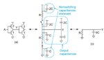
I was confused when calculating effective capacitance at a point. For example,
Point Y should see 2C to gnd and 4C to Vdd. Why we can make it an equivalent circuit to 6c to gnd?
For pmos parasitic cap, it always connected between output and vdd. Why we need to add this into effective capacitance since it never draw current as long as vdd is on.
Point Y should see 2C to gnd and 4C to Vdd. Why we can make it an equivalent circuit to 6c to gnd?
For pmos parasitic cap, it always connected between output and vdd. Why we need to add this into effective capacitance since it never draw current as long as vdd is on.