Continue to Site

Welcome to EDAboard.com

Welcome to our site! EDAboard.com is an international Electronics Discussion Forum focused on EDA software, circuits, schematics, books, theory, papers, asic, pld, 8051, DSP, Network, RF, Analog Design, PCB, Service Manuals... and a whole lot more! To participate you need to register. Registration is free. Click here to register now.

DC Motor Speed Controller

Status
Not open for further replies.

gauravkothari23

Advanced Member level 2
Joined
Mar 21, 2015
Messages
640
Helped
5
Reputation
10
Reaction score
4
Trophy points
1,298
Activity points
6,922
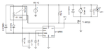
Hi All, I am designed a small 12V 1Amps DC Motor Speed Controller using NE-555 IC
(Circuit Diagram attached).
My question is when i drive the motor at maximum i get 12v but the lowest voltage what i get is 2.50V. but i need 0V at minimum. what changes have to be made to pull down the voltage to 0V at minimum.
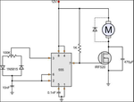
 

Attachments

  • DC Motor Speed Control.png
    DC Motor Speed Control.png
    44.7 KB · Views: 94

Hi,

Not sure if related, I remember an aspect of the 555 with PWMing via pin 5 is that it won't go lower than 1/3 V+ due to the comparators inside. If you get 12V out but can't get it lower than 2.5V maybe it's something you would need to tweak on pin 6. Don't take my word for it, though. I assume the 12V is only obtained because it comes from the supply, not from discharge which is an open collector, and is the comparator that can limit the 555 to 2/3 V+.

Bad suggestion: Could you tie the 0V point by pulling reset low? Not sure what you'd from 2.5V to 0V...

Where's the drive signal into the 555 coming from? It doesn't appear on the schematic.
 

Why do you have the 470 uF capacitor over the FET?
 
  • Like
Reactions: d123

    d123

    Points: 2
    Helpful Answer Positive Rating
Your 1N5815 20A/125V diodes are wrong for the very low current and voltage needed. Use 1N5817 low current and low voltage Schottky diodes instead.
I agree that the 470uF capacitor parallel to the Mosfet is messing up the pulses, get rid of it and use it from +12V to ground instead.

Your meter cannot properly measure the voltage pulses. It is designed to measure DC or low frequency sinewave AC.
 

maybe it's something you would need to tweak on pin 6

Horrors. I named the comparator locations wrong, apologies. 2 is 1/3 V+, 6 is 2/3 V+.
 

I tried changing the capacitor position and diodes...
but still the lowest voltage i am getting is 2.5V
 

2.5V measured in DC range means that the gate pulse duty cycle won't go below 20 %, presuming the circuit is operating correctly.

There are some possible reasons why it may not operate as expected:

- defective MOSFET
- the motor is a brushless DC instead of regular brushed motor as suggested by the schematic

As for the diodes in duty cycle control circuit, people are using low power Si-diode like 1N4148 in this place.
 

Your meter cannot properly measure the voltage pulses.
2.5V measured in DC range means that the gate pulse duty cycle won't go below 20 %, presuming the circuit is operating correctly.
How do you guys know he is using a Volt meter at the gate of MOSFET ? He does not actually mention anything on how he is measuring it. What if he is using a scope ?
 

I'm talking about 2.5V DC motor voltage, as stated by the OP, not gate voltage.

Surely an oscilloscope measurement would be preferred.
 

Hi guaravkothari23,

Could you check you've put this circuit together correctly (no "Oh my God, look where I put that wire/component, I hadn't noticed before." kind of stuff)?

I made it on a breadboard, admittedly using an LED instead of a motor, and a logic level MOSFET - I have some IRF520s but don't see much difference as the circuit should work with most things. It's on a "12V" supply, that gets to about 11.76V. I changed 1k for a 10k, used 1N4148s for the diodes, and I think that schematic may have an error: pin 5 is usually a 0.1uF, not 0.1nF capacitor to ground.

I get with the DMM on DC voltage setting:

LED on: pin 3 and pin 7 = 11.4V, MOSFET drain = 0V
LED off: pin 3 = 5mV, pin 7 = 14mV, MOSFET drain = 10V

Cheap oscilloscope on DC and VMAX settings shows pin 3/7 go from solid line at 10V through squarewave duty cycle that is wide on time then narrower and well-spaced apart on time pulses until it becomes 0V flatline.

That circuit should work AFAIK. It can certainly power an LED :) If you have everything right and it's not going below 2.5V, how about shoving a BJT or another MOSFET between pin 7 and the MOSFET controlling the motor path to ground? Obviously needing to make one P and the other N. It might not work but it might make some difference.

thanks for the testing you have done....
but with load even the output i get is also 0V. but without load i cant drop the voltage below 2.5V
 

You can try a slight modification to the circuit as shown. You will need to replace the 100 k pot with a 500 k and add an additional 100 k resistor to make the adjustment more logarithmic. You can also use a 100 k log pot if you have one. The advantage is that you will have a much lower minimum pulse rate when the pot is set 0 %, but about the same when set to 100 %.

As shown this should give you about a 5X reduction in the average-minimum motor voltage. With your circuit or this variation, you will never get zero volts as there are always some pulses when set to zero.

One other alternative is to use a pot that has a coupled switch. So when you get to zero-off position, you can use the switch to manipulate the reset pin to terminate output pulses.
 

Attachments

  • 555_mot_off.png
    555_mot_off.png
    13.2 KB · Views: 77
  • 555_mot.png
    555_mot.png
    77.1 KB · Views: 82

Hi,

without load i cant drop the voltage below 2.5V

Right, right...but you don't say where you measure 2.5V...and only now you mention that it is with no load - that is not "fair" to other members who try to suggest solutions and who I guess have also assumed the problem was with the circuit configuration in the schematic (from an Instructables, I looked for it) in post #1 with a motor attached.

Come on, dude, you post questions here regularly, try to be a bit more organised when presenting the problem rather than moving the goalposts every few posts, and explain what you're measuring, please.

So, to get to the point, where is the mystery 2.5V when there is no motor attached to the circuit? Also, out of interest, why are you expecting there to be no load on that circuit when it's powered up? Thanks.

_______________________________________________________________________________________________________________________________

E-design,

Hi. That looks like TINA. Did you have to modify three analysis parameters (TR max iteration number, TR truncation error factor and TR maximum time step) to get the 555 to simulate? Thanks.
 

Hi. That looks like TINA. Did you have to modify three analysis parameters (TR max iteration number, TR truncation error factor and TR maximum time step) to get the 555 to simulate? Thanks.

I didn't modify any of the analysis parameters. I just used the standard TINA model in the library. It may be a problem with earlier TINA versions. They were a bit buggy. I am using the latest version 11 at the moment that appear to have a lot fewer problems.

Amazing how they manage to fix most problems only when they release a complete new version (that you need to pay for). Somehow it can't be fixed in minor version upgrades. Very convenient!
 
  • Like
Reactions: d123

    d123

    Points: 2
    Helpful Answer Positive Rating
Status
Not open for further replies.

Similar threads

Part and Inventory Search

Welcome to EDABoard.com

Sponsor

Back
Top