Continue to Site

Welcome to EDAboard.com

Welcome to our site! EDAboard.com is an international Electronics Discussion Forum focused on EDA software, circuits, schematics, books, theory, papers, asic, pld, 8051, DSP, Network, RF, Analog Design, PCB, Service Manuals... and a whole lot more! To participate you need to register. Registration is free. Click here to register now.

[SOLVED] AC Current Measuring -ADC- with Current Transformer H.ow convert the Ac to Dc ?

Status
Not open for further replies.

thannara123

Advanced Member level 5
Joined
Jan 7, 2010
Messages
1,580
Helped
122
Reputation
244
Reaction score
114
Trophy points
1,353
Location
India
Activity points
10,381
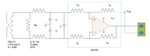
I require to measure AC Current by using CurentTransformer to Microcontroller .


1) 0.5volt would get whenever the load maximum.


what are techniuqe there available ?


https://microcontrollerslab.com/wp-content/uploads/2014/07/difference2.png

[https://microcontrollerslab.com/ac-voltage-measurement-using-microcontroller/]

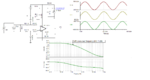
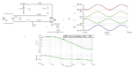
the above link used a differential amplifier ,
I doubts ,

The output of the differential amplifier is also an ac signal ,then how the ADC read it ?

I require lowest components .
 
Last edited:

Hi,

A frequently asked question. Many threads discuss this topic.
When you go through some threads you will see that there are several methods for hardware and software.
Each has it's benefits and drawbacks.

The most precise with low component count and low cost is this solution:
https://www.edaboard.com/showthread.php?t=342472&p=1461486&viewfull=1#post1461486

You say current measurement:
But AC current measurement doesn't say what value you are interested in: RMS, peak, averaged rectified...
With the given circuit you are free to calculate any of these values...with software

Klaus
 
The burden resistor output is very low so cannot use a diode to rectify due to voltage drop of the diode.
How use the signal without converting to dc .
What is the logic behind the differential amplifier ?
 

Hi,

I don't know why you relate output resistor to diode.
My recommended circuit uses no diode, anyway. Therefore there is no problem with a diode.

Differential amplifer:
I've designed a lot of AC current measurement circuits. I think I never used a differential amplifier.
If you read about differential amplifier benefits, then one important is "high input common mode range"...but this is not useful with a CT.
Why did you choose differential amplifier circuit? I assume you've read a document....then read this document again why they recommend a difference amplifier circuit.

Without converting to DC:
Converting to DC uses more components, but you asked about a simple circuit.
Converting to DC generates errors.
Converting to DC can be done in several ways, depending what output value you need.
--> again my question: what value you are interested in?

Klaus
Hello I am mentioning the circuit i have already posted ,Have you look ? https://microcontrollerslab.com/wp-content/uploads/2014/07/difference2.png

Some one using that types circuit .

I am clearly asking my doubts as follows .

Please assume as

If i would get a maximum voltage 0.5volt [from CT].

If I use a diode it drops .7 volt so idont require that .

The given https://microcontrollerslab.com/wp-content/uploads/2014/07/difference2.png
which is used as measuring current .

Here the AC current is directly connected to the OP amp inverting and non inverting Pin ?
what will the output ? How the Microcontroler detect it .
 

Hi,

Sadly you don't answer any question.

If i would get a maximum voltage 0.5volt [from CT].
A CT is - like is name says - a current transformer.
I'ts output is not voltage, but current.
Just the use of a burden resistor generates voltage according Ohm's law: V = I x R

Now your difference amplifier is a voltage amplifier (with an AC input voltage). It can not be used as current amplifier nor can it be used as current to voltage amplifier without the use of a burden resistor.

And there is no diode.... so what diode do you refer to?

I'll be back after you give useful informations, specifications, circuits, links...

Klaus
 
Yes sir
d36d05cf-5c9a-4f0d-8197-e70ea304bd4f.jpg

But the voltage accross from the burden resistor also in sine wave how to put it MCU .
It need to convert ? I want to sample 10ms wave [because input signal is 50hz].
This is I tried to ask the same in the first post.
I dont have a Osciloscope :sad:
 
Last edited:

You can use the circuit below and scale it to your needs. It uses a 2.5 V offset so that the zero of your current measurement will be at 2.5 VDC. You can easily handle that in code to get your maximum and minimum readings.

The burden resistor that KlausST talked about is R1 in the diagram. It converts the current produced by the CT, to a voltage. The bandwidth of the circuit is about 300 Hz.
 

Attachments

  • CT_amp.png
    CT_amp.png
    55.9 KB · Views: 313
You can also go with a simpler circuit, but you lose the common-mode rejection advantage of the differential circuit.
 

Attachments

  • CT_amp_se.png
    CT_amp_se.png
    50.6 KB · Views: 213
Hi,

A CT has isolated output, therefore you don't need a circuit with wide common mode input voltage range.
You may freely choose the common mode voltage as you like.

I really don't know what benefit a differential amplifier brings in combination with a CT.

Klaus
 
Klaus, I was thinking about noise pickup in this instance.
 
Hi,

A CT output node including burden resistor usually is low impedance. In my eyes the introduction of noise in this node is less than with an additional Opamp circuit.

With the CT there is no signal conditioning necessary (gain adjust via burden resistor, offset adjust via voltage divider)...
Therefore any additional circuitry will introduce additional errors.

******
But the shown circuit shows a voltage measurement. With high impedance voltage dividers, high common mode input voltage voltage range, adding output offset.... --> here a differential amplifier is very useful.

Klaus
 

TI uses a similar differential input circuit in one of their application notes dealing with current sensing from a CT.
 

Attachments

  • diff_amp.png
    diff_amp.png
    23.5 KB · Views: 245

Hi,

Here both CT connections are very high impedance...why? Does it make sense? In my eyes not. This just makes the wiring prone of introduced noise.
It seems the burden is close to the sensor....and there is a lot of wiring between CT and amplifier (shown by the two series resistors). Why?
Why not placing the burden close to the ADC? Then - since the CT is "current output" - the wiring resistance may not harm the signal precision.

Maybe there is a good cause for this circuit we don't know.

My personal opinion: Making the nodes high impedance ... creates the need for a differential amplifier ... maybe to improve selling of the INA.
I design measurement equipment for industrial plants. One system is for a phase controlled 2500V, 6000A RMS (dV/dt is about 3500V/500ns max) system.
Simple twisted, shielded cable to the CTs, burden close at the ADC. And although I increased bandwidth for my true_RMS measurement by a factor of 100 against usual RMS measurement units (to improve regulation loop stability) my output signal is stable down to 0.1% Fs. It works for many years now, without problems.
I even did extra EMC tests .... all results are very relaxed.

For sure I use differential amplifier circuits in other designs - where I (or better: the signals) gain from it's benefits.

But the OP and any other person is free to choose his/her own solution. No need to follow my recommendations.

Klaus
 
  • Like
Reactions: CataM

    CataM

    Points: 2
    Helpful Answer Positive Rating
Sorry for the silly question .

The output voltage from the CT across the Burden resistor is in AC nature , In here am doubting
Which one is the phase and neutral ?

With the the two wire how to calculate the gain with the equation Vo = A(V1 - V2 )?
How guess as which one is positive and negative in V1 and V2?
How to assume with respect to each other ?

sorry for this like a foolish doubts .
 

The lowest cost/component solution is to ground one side of the CT secondary, add the burden resistor across it, then take the other side to a precision rectifier circuit. At it's simplest it is just an inverting amp with a diode in series with it's output and the same diode type in it's feedback path. The amp offsets the diode voltage drop so it is accurate at voltages down to (or very close to) zero. Search for 'precision rectifier' for more information.

Hint: https://www.linear.com/solutions/1608

Brian.
 

That could work as long as you don't need to measure specific peaks on a positive or negative half-cycle, otherwise you will need to identify the one you are interested in.

DC offsets can happen under unusual or fault conditions.
 

Attachments

  • ac_peaks.png
    ac_peaks.png
    10.1 KB · Views: 156

You can also go with a simpler circuit, but you lose the common-mode rejection advantage of the differential circuit.

I tried to simulate the same circuit in Proteus ,Unfortunately i am not getting a sine wave why ?

2.JPG
1.JPG
 

I tried to simulate the same circuit in Proteus ,Unfortunately i am not getting a sine wave why ?

You are using the same ground reference, both for the sine wave source and for the analog circuit.
The Oscilloscope use the standard GND as its own reference.
 

Status
Not open for further replies.

Part and Inventory Search

Welcome to EDABoard.com

Sponsor

Back
Top