Continue to Site

Welcome to EDAboard.com

Welcome to our site! EDAboard.com is an international Electronics Discussion Forum focused on EDA software, circuits, schematics, books, theory, papers, asic, pld, 8051, DSP, Network, RF, Analog Design, PCB, Service Manuals... and a whole lot more! To participate you need to register. Registration is free. Click here to register now.

Booster circuit to square wave peak to peak voltage

Status
Not open for further replies.
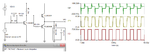
want to amplify a square wave with a frequency of 1Mhz and peak to peak voltage 750 milivolts,now am using ua741 opamp am not getting perfect square wave at the output side,please suggest me which opamp i should use to amplify 1Mhz signal.

I suggest you look at the data sheet for the 741 and see how well it performs at 1MHz!

Brian.
 

Hello,
i tried the circuit again i am getting waveform up to 600Khz,750mv input,after frequency exceeds 600Khz waveform diminishes as shown in the below attachment IMG_20180106_124945.jpgIMG_20180106_124518.jpg

- - - Updated - - -

hello,
i tried once again but up to 600Khz i am getting waveform but above 600Khz i am not getting square wave,i have posted the wave form and circuit as you asked.
IMG_20180106_124945.jpg,IMG20180106130034.jpg

Regards,
Rashmi HM
 

Hi,

In your picture I miss a clean GND wiring...
and I miss the power supply capacitors. Use a 10uF..100uF bulk capacitor AND a 100nF ceramics capacitor as close as possible at the IC supply pins.

Klaus
 

You don't want the 50 Ohm resistor in series with the input. On my diagram it represents the output impedance of the function generator. Connect directly to the 120 Ohm point, otherwise you will half the input drive to the base. Put the 470 Ohm resistor between pin 5 and GND on the 555. The capacitors mentioned by KlausST is also very important for good operation.

I can't see all the connections around the 2N3904. Make sure they are correct. I can't see where pin 1 connects to GND.
 

Hi,
i tried the second circuit with transistors i am getting the amplified output but if i increase the input voltage more then 9v to get increased voltage at output the 1.2 K resistor is getting heated up what would be the reason or i should put high watt resistor because am using quarter watt resistor.
 

Hi,

P = V x V x R
--> V = sqrt(P / R)
In your case: V = sqrt( 0.25W x 1200Ohms) = sqrt(300) V = about 17V.
17V DC, or 17V RMS.

--> with a 5V supply you can't overheat the resistor (when used in typical environment)

You speak of "heat". Please check power supply voltage and resistor value.

Klaus
 

Are you trying to get more than 5 Vpp at the output? I thought you said that your transducer had a maximum rating of 5 Vpp? If you want the increased drive level, then you obviously have to use the design without the 5V6 clamp zener.

With the load you specified, that resistor should not get near 1/4 W.

Can you show a scope capture of your 750 mV input pulse, if it is not at a standard 50% duty cycle?
 

Attachments

  • res_pwr.png
    res_pwr.png
    24 KB · Views: 66

Status
Not open for further replies.

Part and Inventory Search

Welcome to EDABoard.com

Sponsor

Back
Top