Continue to Site

Welcome to EDAboard.com

Welcome to our site! EDAboard.com is an international Electronics Discussion Forum focused on EDA software, circuits, schematics, books, theory, papers, asic, pld, 8051, DSP, Network, RF, Analog Design, PCB, Service Manuals... and a whole lot more! To participate you need to register. Registration is free. Click here to register now.

[SOLVED] SIRC Decoding not working

Status
Not open for further replies.

baileychic

Advanced Member level 3
Joined
Aug 2, 2017
Messages
728
Helped
56
Reputation
112
Reaction score
57
Trophy points
28
Activity points
7,033
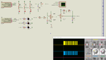
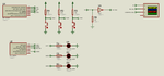
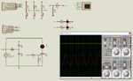
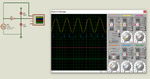
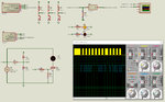
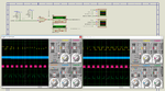
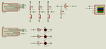
SIRC Decoding not working. What is the problem. Find the attached circuit. This is the code of hexreader. I found this code at libstock and mikroe forum. I modified it for PIC12F683 but decoder is not working.

Transmitter code.


Code C - [expand]
1
2
3
4
5
6
7
8
9
10
11
12
13
14
15
16
17
18
19
20
21
22
23
24
25
26
27
28
29
30
31
32
33
34
35
36
37
38
39
40
41
42
43
44
45
46
47
48
49
50
51
52
53
54
55
56
57
58
59
60
61
62
63
64
65
66
67
68
69
70
71
72
73
74
75
76
77
78
79
80
81
82
83
84
85
86
87
88
89
90
91
92
93
sbit SW1 at GP0_bit;
sbit SW2 at GP1_bit;
sbit SW3 at GP3_bit;
 
sbit IR_Encode_Pin at GP2_bit;
 
unsigned int irCode = 0;
unsigned char flagRegister = 0;
 
sbit startPwmFlag at flagRegister.B0;
 
void sendIRData(unsigned int irData) {
    unsigned char i = 0;
    unsigned int mask = 0x02;
 
    IR_Encode_Pin = 1;
    //PWM1_Start();
    Delay_us(2400);
    IR_Encode_Pin = 0;
    //PWM1_Stop();
    Delay_us(600);
 
    for(i = 0; i < 12; i++) {
       if(irData & mask){
          IR_Encode_Pin = 1;
          //PWM1_Start();
          Delay_us(1200);
          IR_Encode_Pin = 0;
          //PWM1_Stop();
       }
       else {
          IR_Encode_Pin = 1;
          //PWM1_Start();
          Delay_us(600);
          IR_Encode_Pin = 0;
          //PWM1_Stop();
       }
 
       Delay_us(600);
       mask <<= 1;
    }
    
    Delay_ms(45);
}


void main(){
 
    asm clrwdt
    OPTION_REG = 0x8F;
    CMCON0 = 0x07;
    ANSEL = 0x00;
    TRISIO = 0b00001011;
    GPIO = 0x00;
    
    Delay_ms(100);
 
    //PWM1_Init(38000);
    //PWM1_Set_Duty(127);
 
    while(1){
 
         asm clrwdt
         
         if(SW1 == 0){
           Delay_ms(50);
           if(SW1 == 0){
              irCode = 0b1010001100101; //0110010  10100
              startPwmFlag = 1;
           }
         }
         else if(SW2 == 0){
           Delay_ms(50);
           if(SW2 == 0){
              irCode = 0b1110001100111;
              startPwmFlag = 1;
           }
         }
         else if(SW3 == 0){
           Delay_ms(50);
           if(SW3 == 0){
              irCode = 0b1111001101001;
              startPwmFlag = 1;
           }
         }
 
         if(startPwmFlag){
            sendIRData(irCode);
            startPwmFlag = 0;
         }
    }
}


Receiver code.


Code C - [expand]
1
2
3
4
5
6
7
8
9
10
11
12
13
14
15
16
17
18
19
20
21
22
23
24
25
26
27
28
29
30
31
32
33
34
35
36
37
38
39
40
41
42
43
44
45
46
47
48
49
50
51
52
53
54
55
56
57
58
59
60
61
62
63
64
65
66
67
68
69
70
71
72
73
74
75
76
77
78
79
80
81
82
83
84
85
86
87
88
89
90
91
92
93
94
95
96
97
98
99
100
101
102
103
104
105
106
107
108
109
110
111
112
113
114
115
116
117
118
119
120
121
122
123
124
125
126
127
128
129
130
131
132
133
134
135
136
137
138
139
140
141
142
143
144
145
146
147
148
149
150
151
152
153
154
155
156
157
158
159
160
161
162
163
164
165
166
167
168
169
170
171
172
173
174
175
176
177
178
179
180
181
182
183
184
185
186
187
188
189
190
191
192
193
194
195
196
197
198
199
200
201
202
203
204
sbit LED1 at GP0_bit;
sbit LED2 at GP1_bit;
sbit LED3 at GP4_bit;
 
//sbit IR_Decode_Pin at GP2_bit;
 
sbit ir_in at GP2_bit;                      // Infrared receiver input
sbit ir_in_direction at TRISIO2_bit;         // Infrared receiver input
 
// global variables
char fb_string[10];                // just a place to convert numbers to strings
char irbyte;                       // assemble a byte of IR
char cmd;                          // current command character from UART or PORTD
unsigned int cnt;                  // expands 16 bit counter to 32 bit - not used here
unsigned int retint;               // general purpose integer
//char keephex[3];                   // store hex value as ascii
unsigned char ir_byte;
char ir_toggle;                    // toggle bit value
unsigned char ir_result[11];
char mmc_zeros;
 
void sony_print(void);
int get_mark(void);
int get_space(void);
unsigned char get_sony_byte(char nbits);
 
//Timer1
//Prescaler 1:1; TMR1 Preload = 64936; Actual Interrupt Time : 600 us
void InitTimer1() {
    T1CON = 0x01;
    TMR1IF_bit = 0;
    TMR1H = 0xFD;
    TMR1L = 0xA8;
    TMR1IE_bit = 1;
}
 
void interrupt() {                 // interrepts are here, but serve no function yet
    if((TMR1IE_bit) && (TMR1IF_bit)) {                // handle timer 1 overflow
        cnt++;                       // Increment counter - gives extra 2 bytes counter option
        TMR1IF_bit = 0;              // Clear TMR1IF
        TMR1H = 0xFD;
        TMR1L = 0xA8;
    }
 
    if((INTE_bit) && (INTF_bit)) {                  // handle interrupt on B0 pin
        INTF_bit = 0;               // clear interrupt
        INTEDG_bit = ~INTEDG_bit;
    }
}
 
/*
// Sony Remote 40kHz 7 bits command (LSB first) then 5 bits address
// there are also 15 bit and 20 bit versions of Sony protocol
//
// 40kHz 7 bits command (LSB first) then 5 bits address
// 2.4ms mark=start
// 0.6sp, 0.6 mark = 0
// 0.6sp, 1.2 mark = 1
//
// tv               address=01
// vcr1             address=02
// vcr2             address=03
// radio/cd         address=04
// laser disc       address=06
// surround sound   address=0c
// tuner            address=0d
// amp              address=10 (theatre / cassette / tuner)
// cd player        address=11
// equaliser        address=12
// HDMI control     address=17
// dvd              address=1a
 
// print unsigned char as hex
void hexout(unsigned char hexval){
int temp_hex;
char hextxt[7];
 
    temp_hex = hexval;                     // to integer
    IntToHex(temp_hex, hextxt);            // integer to ASCII hex
    keephex[0] = hextxt[2];                // store ascii hex for later
    keephex[1] = hextxt[3];
    keephex[2] = 0;                        // null terminate
}
// print out Sony values
 
void sony_print(void){
signed int temp_ir;
 
    while(1){
        while(ir_in);                         // wait for IR to go low
 
        temp_ir = get_mark();
        if ((temp_ir > 130) && (temp_ir < 200)){       // expect 2.4mS mark
            ir_result[0] = get_sony_byte(7);           // 7 bit command
            ir_result[1] = get_sony_byte(5);           // 5 bit address
            Lcd_Out(2,1, "cmd=   addr=    ");          // Print text to Lcd, 2nd row, 1st column
            hexout(ir_result[0]);
            Lcd_Chr(2,5,keephex[0]);
            Lcd_Chr(2,6,keephex[1]);
            hexout(ir_result[1]);
            Lcd_Chr(2,13,keephex[0]);
            Lcd_Chr(2,14,keephex[1]);
            Delay_ms(10);             // wait for repeat messages to clear
        }
    }
 
}
*/
 
void sony_print(void){
    signed int temp_ir;
 
    while(1){
        while(ir_in);                         // wait for IR to go low
        temp_ir = get_mark();
        
        if ((temp_ir > 130) && (temp_ir < 260)){       // expect 2.4mS mark
            ir_result[0] = get_sony_byte(7);           // 7 bit command
            ir_result[1] = get_sony_byte(5);           // 5 bit address
            Delay_ms(10);                              // wait for repeat messages to clear
            
            if(ir_result[0] == 0b1010001) {
                 LED1 = ~LED1;
            }
            else if(ir_result[0] == 0b1110001) {
                 LED1 = ~LED1;
            }
            else if(ir_result[0] == 0b1111001) {
                 LED1 = ~LED1;
            }
            
            ir_result[0] = 0;
        }
    }
 
}
 
// get one byte of Sony
unsigned char get_sony_byte(char nbits){
    char n;
    unsigned char ir_byte;
    signed int temp_ir;
 
    ir_byte = 0;
                                      // initialise
    for(n = 0; n < nbits; n++){
        temp_ir = get_space();                    // expect ~510uS
        temp_ir = get_mark();                     // 650uS = 0, 1.2uS = 1
        ir_byte >>= 1;
        
        if(temp_ir > 60) {                        //
            ir_byte += 0x80;
        }
    }
    
    ir_byte >>= 8 - nbits;                          // convert 5/7 bits to 8
    
    return ir_byte;
}
 
// get IR mark time (low)
int get_mark(void){
    TMR1H = 0;
    TMR1L = 0;
    while(!ir_in);
    retint = TMR1L;
    retint += (unsigned int)TMR1H << 8;
    
    return retint;
}
 
// get IR space time (high)
int get_space(void){
    TMR1H = 0;
    TMR1L = 0;
    while(ir_in);                        // wait for IR to go low
    retint = TMR1L;
    retint += (unsigned int)TMR1H << 8;
    
    return retint;
}
 
void main(){
 
    asm clrwdt
    OPTION_REG = 0x8F;
    CMCON0 = 0x07;
    ANSEL = 0x00;
    TRISIO = 0b00000100;
    GPIO = 0x00;
 
    Delay_ms(100);
    
    InitTimer1();
    INTE_bit = 1;
    PEIE_bit = 1;
    GIE_bit = 1;
    cnt = 0;
 
    while(1) {
         asm clrwdt
         sony_print();
    }
}


Attachments

  • SIRC Encoder And Decoder - Rev A1.rar
    59.3 KB · Views: 112
  • SIRC Encoder and Decoder.png
    SIRC Encoder and Decoder.png
    20.3 KB · Views: 268

Your hardware circuit will not work.

The transmitting PIC sends out 40kHz modulation with the SIRC signal providing the modulation.

The receiver expects 40kHz modulation to be stripped off by the 3-pin IR receiver IC and pure SIRC signal to be fed to the PIC.

EDIT : on second thoughts.... ignore all of the above. I see that you have modified transmitter code to send raw SIRC without modulation.

I will look further into the code when I get the chance - though I will use real hardware, not a simulator.

- - - Updated - - -

In the mean time, I attach PIC12F683 receiver code.
 

Attachments

  • IR683sony.zip
    19.7 KB · Views: 111
Last edited:
My hardware is correct. My real hardware uses TSOP1738 and my PWM (carrier) frequency is 38 KHz. I am testing in both Proteus and hardware and both are not working. In Proteus I don't know how to remove 38KHz carrier and feed the carrier stripped signal to INTx pin and so I have not used carrier in Proteus. If I get it working in Proteus then I will add carrier frequency and test it on hardware.

In the code (project) you posted where is the 600 us Timer Initialization and Timer ISR ?

Also provide matching encoder code.

- - - Updated - - -

The receiver code that you posted works will with my transmitter code. I got it working. Thank you hexreader. Good work hexreader.

- - - Updated - - -

Hi hexreader

I am very thankful for your help. I want to provide you a licence for mikroC PRO PIC Compiler. I have an extra licence. You have disabled PM and I can't send you the Key in PM. Can you instead email me so that I can send you a mikroC PRO PIC licence through email ?
 
Last edited:

That is a really kind offer, but I already have dongle licence.

The thought is much appreciated though.

No thanks are necessary, as I program purely for fun.

Libstock already contains tested versions of PIC12F683 transmitter and receiver for Sony SIRC (may take some searching). Interrupts are not needed for such a simple project. 600uS timer is not needed because I use completely different way of decoding to most other programmers.

Glad it all worked out for you..... :)
 
Someone else will have to answer this one. I know nothing of Proteus.
 
@hexreader.

What changes I have to make to the receiver code to make it work with PIC12F675 running at 4MHz Internal Oscillator ?
 

but that did not give me demodulated signal in Proteus.
I'm neither using Proteus regularly, I mean to remember that digital signals don't have an assigned analog level and are ignored in the "analog" circuit analysis. Component with DA interface feature needed, review the manual.

A mono-flop pulse extender is probably the better way to achieve what you want.
 
@FvM

Can you show me an example circuit of mono-flop pulse extender ?

Do you mean I have to use a circuit like this which uses NE555 ?

https://www.indiabix.com/electronics-circuits/555-missing-pulse-detector/

If yes, what are the component values ? How to calculate them ?

- - - Updated - - -

SIRC 0 bit = 600 us ON and 600 us OFF.
SIRC bit 1 = 600 us ON and 1200 us OFF.

So, when calculating time constant what time value I have to choose ? This I need to calculate R and C values.

- - - Updated - - -

@hexreader.

I made changes to code and now it is working with PIC12F675. Here is the Proteus simulation.
 

Attachments

  • Remote Control and Receiver - 12F675.rar
    12.8 KB · Views: 105
  • Remote Control with Receiver.png
    Remote Control with Receiver.png
    20 KB · Views: 164
Last edited:

Now I have a new issue with this project but it is not related to SIRC decoding but it is related to ZCD not working but as it is related to the same project I am asking the question here. Mods if you think I have to ask the question in a different thread then move this new post to a new thread.

Check the Proteus simulations. Also circuit as image files attached. The ZCD circuit as a standalone is working in ZCD.pdsprj but same ZCD circuit in "Remote Control and Receiver.pdsprj" is not working. I need to control a triac using remote control receiver and I need a ZCD circuit for that. Is there any other way to properly fire the triac without using ZCD circuit and MOC3021 (opto triac) ?
 

Attachments

  • Remote Control and Receiver.rar
    33.7 KB · Views: 109
  • remote control with receiver.png
    remote control with receiver.png
    116.4 KB · Views: 126
  • zcd.png
    zcd.png
    95.3 KB · Views: 119

SIRC decoding is working fine now. ZCD still not working in the remote control circuit.

I made TSOP1738 Proteus VSM model. It is working fine. It is provided in the attached file. Test the simulation.
 

Attachments

  • Remote Control and Receiver - Rev A4.rar
    27.4 KB · Views: 115
  • Proteus Simulation Result.png
    Proteus Simulation Result.png
    120.7 KB · Views: 245

Updated and final Proteus VSM model for TSOPXXXX devices attached with test simulation file. Now you can specify the carrier frequency between 30KHz and 56KHz. One model works for all carrier frequencies.

Use it to make IR Remote control and receiver projects.
 

Attachments

  • TSOPxxxx.rar
    25.5 KB · Views: 109

Updated TSOPXXXX Proteus VSM model attached with Simulation file. Test it and report bugs. Now both licensed users of Proteus and crac**d version users can use the model.
 

Attachments

  • TSOPXXXX VSM MODEL - REVISION A2.rar
    20 KB · Views: 94
  • TSOPXXXX-ADV VSM MODEL TEST.png
    TSOPXXXX-ADV VSM MODEL TEST.png
    132 KB · Views: 166

Status
Not open for further replies.

Similar threads

Part and Inventory Search

Welcome to EDABoard.com

Sponsor

Back
Top