ICdesignerbeginner
Member level 5
Hi
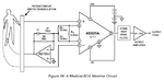
I am attaching a ECG block diagram. I have a question in my mind In the lock diagram a pre-amplifier is placed before the filter block but when we try to design a filter normally OTA-C filter then we try to take small vgs so that we can achieve linearity. If pre-amplifier is placed before filter the pre-amplifier will provide a large amplified signal which will go to the filter and the filter input will be large. For reducing the input signal in filter different attenuation techniques are used so that we can get low vgs and improved linearity. Why a filter block is placed after a pre-amplifier because first we increase the signal by using pre-amplifier then we try to decrease the amplified signal to get low vgs to improve linearity in filter.
First increasing and then using techniques to decrease signal I can understand. Cant a filter be placed directly then amplify may be.
Can some one help me in understanding this.