Continue to Site

Welcome to EDAboard.com

Welcome to our site! EDAboard.com is an international Electronics Discussion Forum focused on EDA software, circuits, schematics, books, theory, papers, asic, pld, 8051, DSP, Network, RF, Analog Design, PCB, Service Manuals... and a whole lot more! To participate you need to register. Registration is free. Click here to register now.

[General] Vcc vs. Vdd vs. Gnd and a little help

Status
Not open for further replies.

RBraverman

Newbie level 3
Joined
Dec 16, 2017
Messages
3
Helped
0
Reputation
0
Reaction score
0
Trophy points
1
Activity points
33
Hope this is the right place ... and no laughing please, at least not to my face ...

I have not played with circuits for a very LONG time, and now I find myself confused on what should be an easy point.

I'm replacing the display LCD in my wifes favorite radio, which is about 12 years old. Part of the pin-out is:

Vdd

Gnd


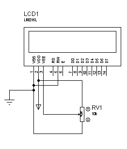
The replacement is using VSS/VDD/V0 -

Vss can not be ground - correct? Everything I've read claims/states Vdd is/would be Gnd and Vss supply.

It's crazy, as the more I read the more this easy transformation becomes difficult! AND it shouldn't be.

Anyone care to hold my hand?
 

Hi,

The internet is full of informations - for almost every problem.
Use an internet search engine: https://lmgtfy.com/?q=display+vcc+vss

One of the first hits is this:
https://focuslcds.com/journals/lcd-voltage-inputs-for-lcd-displays-explained/
I assume this exlains all your questions.

And there is the LCD datasheet.
It may tell you:
VSS = 0V. --> 0V means it is your voltage measurement reference.
And the description and voltage levels if all the other signals..

And there are example circuits available:
Like here: https://www.edaboard.com/showthread.php?t=194246&p=824737&viewfull=1#post824737
56_1292828437.png

Those schematics - at least - give you a hint how to connect a display.

Klaus
 

Some of this is from history. VCC was the Collector supply in the days when bipolar transistors ruled the World, VDD was the Drain equivalent when MOS devices became more prevalent. In almost all cases they both refer to the positive supply rail although this isn't mandatory. In some circuits both may exist as different supply lines.

VSS is generally the Source, 0V or negative side of the supply.

I would guess V0 and VEE are equivalent terms, they relate to an additional supply needed on most LCD modules to set the contrast level. It is made adjustable to cater for different viewing angles and to allow temperature compensation so the viewing angle remains constant as the temperature changes. In most circumstances, the voltage on it is close to VSS but it can be negative with respect to VSS for maximum contrast. Note that on most modules the contrast range is very limited and increasing the contrast beyond a certain point brings the 'off' pixels into view as well as the 'on' ones. This is often seen as 'filled boxes' instead of characters.

Brian.
 
  • Like
Reactions: Garyl

    Garyl

    Points: 2
    Helpful Answer Positive Rating
Vss = Voltage Source Source
VDD = Voltage Drain Drain
VCC = Voltage Collector Collector
VEE = Voltage Emitter Emitter
VBB = Voltage Base Base
 

Hi,

The internet is full of informations - for almost every problem.

Really? Is it REALLY as good as they say?


First that's REALLY cute, I just LOVE it.
Secondly, did you really think, I realize I didn't state otherwise, that I just popped in here and asked the question I did WITHOUT searching? I've been at it for a solid week now.

One of the first hits is this:
https://focuslcds.com/journals/lcd-voltage-inputs-for-lcd-displays-explained/
I assume this exlains all your questions.

Had I come across that, , I would have had no need for asking the question here. The Vss vs. Gnd was the sticker.

My fault for not posting a pic of the radio and the LCD, so that what I thought I'd posted, in fact I hadn't. They aren't labeled the same, (the LCD being new, and the radio being almost 15 years old) which made the match up difficult.


And there is the LCD datasheet.
It may tell you:
VSS = 0V. --> 0V means it is your voltage measurement reference.
And the description and voltage levels if all the other signals..

Why didn't you just get to that?
 

Some of this is from history. VCC was the Collector supply in the days when bipolar transistors ruled the World, VDD was the Drain equivalent when MOS devices became more prevalent. In almost all cases they both refer to the positive supply rail although this isn't mandatory. In some circuits both may exist as different supply lines.

VSS is generally the Source, 0V or negative side of the supply.

I would guess V0 and VEE are equivalent terms, they relate to an additional supply needed on most LCD modules to set the contrast level. It is made adjustable to cater for different viewing angles and to allow temperature compensation so the viewing angle remains constant as the temperature changes. In most circumstances, the voltage on it is close to VSS but it can be negative with respect to VSS for maximum contrast. Note that on most modules the contrast range is very limited and increasing the contrast beyond a certain point brings the 'off' pixels into view as well as the 'on' ones. This is often seen as 'filled boxes' instead of characters.

Brian.

The moderators will have edited or deleted (or banned me) for my reply to KlausST, so I'll just thank you VERY much for your answer. The difference between the radio and the replacement LCD is about 15 years and the labeling could NOT have been much different - I was stuck on the Vss on the LCD and Ground on the Radio.

Thanks again!
 

Hi,

In post#1 you don't show any effort on your own. No reference to documents, no links, no sources of informations.
There are no detailled, no objective informations, only vague ones.

Everything I've read claims/states Vdd is/would be Gnd and Vss supply.
You say everything. Is this true?
Maybe some informations say so. But then we need to kniw the context to validate this information.
If you find some wrong informations, then you should contact the author to correct it.

This is no unusual process. You may find several threads here in this forum where I (or others) gave wrong informations.
And it's good habit from other users to indicate such mistakes...

Why didn't you just get to that?
Because only you have the information about the manufacturer of the display and the exact device type.

******

No post here will be edited by moderators to modify the meaning of the original post.
No post will be deleted here as long as it complies with forum rules.
No user will be banned just out of mood of a single moderator. There must be an obvious misuse of the forum, otherwise a couple of moderators discuss how to behave.

I see no need to edit your post, no need to ban you, not even to give you an infraction...everything is OK.

Klaus
 
  • Like
Reactions: Garyl

    Garyl

    Points: 2
    Helpful Answer Positive Rating
VCC and VDD are for positive voltage, and VSS and VEE are for ground, Vcc is often applied to BJT collectors, Vee to BJT emitters, Vdd to FET drains, and Vss to FET sources.
well google can be more helpful for detail information.
 

@ RAHUL_KUMAR

What about PNP transistors and PMOSFET ?
 

Status
Not open for further replies.

Similar threads

Part and Inventory Search

Welcome to EDABoard.com

Sponsor

Back
Top