Continue to Site

Welcome to EDAboard.com

Welcome to our site! EDAboard.com is an international Electronics Discussion Forum focused on EDA software, circuits, schematics, books, theory, papers, asic, pld, 8051, DSP, Network, RF, Analog Design, PCB, Service Manuals... and a whole lot more! To participate you need to register. Registration is free. Click here to register now.

How to improve settling time in a low pass filter

Status
Not open for further replies.

Zeinabenaz

Newbie level 5
Joined
Jul 19, 2017
Messages
8
Helped
0
Reputation
0
Reaction score
0
Trophy points
1
Activity points
66
Imporve settling time in low pass filter
Capture.PNG
hi
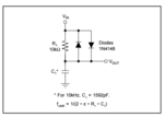
can someone analyze this circuit for me?
you can see in https://www.ti.com/lit/an/sboa011/sboa011.pdf
I think the 10kohm resistor must be short circuit with diode when it is on and charged time and cutoff frequency must be changed(tua=Ron*c Ron is diode forward biased impedance) ,but in document and when I simulation this circiut I see that fc=10khz and tua=10kohm*c

I could not analysis passive low pass filter for this document
I hope to guide me
 

Re: Imporve settling time in low pass filter

It's a non-linear circuit, you can't apply linear network analysis methods. You need nonlinear differential equations respectively transient analysis of a circuit simulator for an exact analysis.

The operation of the circuit is verbosely discussed in the paper, what are you missing particularly?

Saying the nonlinear filter has "improved settling time" may hide it's disadvantages, e.g. passing not only useful signals but also noise exceeding the diode threshold.
 

Re: Imporve settling time in low pass filter

Hi!
You are right, when Vin is a big voltage step, so that the voltage drop on the diode(Vd) is bigger than it's on voltage(Von), the time constant is Ron*C. The capacitor is quickly charged until Vd<Von. Then the time constant becomes RC.

You can see this in simulations by putting a big R, really big R(1G or even bigger :D), and running a transient simulation. Of course Vin should be a pulse signal with high enough amplitude.

In an AC simulation the PSF is first calculated, and than the circuit is liniarized around that point, so you can't observe the diodes going on-off. I personaly think they allways stay off, and the cutoff frequency in this case, is allways 2*pi*R*C.
 

Re: Imporve settling time in low pass filter

Diodes have an exponential V/I characteristic rather than a constant "Ron".

For a rough estimation, I would assume an ideal diode characteristic with e.g. 600 mV forward voltage. Respectively the low pass is bypassed for |Vin - Vout| > 600 mV.
 

Status
Not open for further replies.

Similar threads

Part and Inventory Search

Welcome to EDABoard.com

Sponsor

Back
Top