jeremeejoseph
Newbie level 1
Good day! I'm not quite sure If I came at the right place to post this thread.
The title itself says the main concern. I am new to studying digital logic design. I would like to design a 5-bit sequential multiplier with 5-bit operands (multiplier and multiplicand) that would be used for the input. There are some certain conditions that I need help with.
Input:
A: 5-bit input which is an operand to the 5-bit sequential multiplier.
B: 5-bit input which is an operand to the 5-bit sequential multiplier.
START: High-asserted 1-bit input which initiates the multiplication process. If START is asserted for 1 clock cycle, the multiplication process starts. START can be de-asserted once the multiplication has started.
RESET: Low- asserted 1-bit input which initializes the flip-flops.
Output:
P: 10-bit output which the product of A is and B.
DONE: High-asserted 1-bit output which asserts whenever the multiplication is finished. Once DONE asserts, the current product should be present in the P output. The DONE output will be held asserted until another operation is requested (START is asserted again)
BUSY: High-asserted 1-bit output which asserts whenever a multiplication is currently being performed by the multiplier.
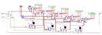
I have here a 4-bit design. It uses 8-bit shift registers, 4-bit counters and some adders. But it seems to be a long process and has complications.
What could be the best possible way to deal with the design by simulation?
The title itself says the main concern. I am new to studying digital logic design. I would like to design a 5-bit sequential multiplier with 5-bit operands (multiplier and multiplicand) that would be used for the input. There are some certain conditions that I need help with.
Input:
A: 5-bit input which is an operand to the 5-bit sequential multiplier.
B: 5-bit input which is an operand to the 5-bit sequential multiplier.
START: High-asserted 1-bit input which initiates the multiplication process. If START is asserted for 1 clock cycle, the multiplication process starts. START can be de-asserted once the multiplication has started.
RESET: Low- asserted 1-bit input which initializes the flip-flops.
Output:
P: 10-bit output which the product of A is and B.
DONE: High-asserted 1-bit output which asserts whenever the multiplication is finished. Once DONE asserts, the current product should be present in the P output. The DONE output will be held asserted until another operation is requested (START is asserted again)
BUSY: High-asserted 1-bit output which asserts whenever a multiplication is currently being performed by the multiplier.
I have here a 4-bit design. It uses 8-bit shift registers, 4-bit counters and some adders. But it seems to be a long process and has complications.
What could be the best possible way to deal with the design by simulation?