d123
Advanced Member level 5
JFET VGS(off) test board minimum VDS needed question
Hi,
I have some JFETs and would like to check VGS(off) on some to find roughly what it is on them to avoid those surprises of ...it could be -1.7V, it could be -2.9V... but you don't know until it's soldered on the board - not helpful.
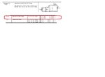
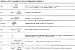
I want to use a homemade test set-up following the Glossary of JFET Measurement Parameters AN-6608 method on page 2 of the app note. This one in the image below, also the datasheet bit about VGS(off) for the xxxx5457 FET is there:

It says 15VDS and 10nA on the datasheet. I haven't a hope of making a 700M resistor to get 10nA from a 7V or if pushed 15V supply, so 5M trimpot or 10M fixed will have to do. Off to a bad start.
I can use a 15V power supply, but would like to use a ~7V supply for VDS and to power a 7660 charge pump inverter into a trimpot into tthe gate to make sure I can get the -0.5V to -6V it says on the datasheet. I'm guessing if a graph says -1.8V typical VGS(off) neither -0.5V nor -6V is likely. Or are JFETs that come in one lot/batch that "bad"/unpredictable?
Main question: Can a 7V supply be used to get a reasonable idea of what VGS(off)s I have in the section of reel I bought, or does VDS have some effect on VGS(off)?
I want to know because the simulation program 2N5457 model seems pretty identical to the physical component MMBF5457. So far, the first three I used in real circuits were ~-2.9V and the fourth was ~-1.7V. Pretty desperate to design some simple circuits without unpleasant surprises like that again. e.g. I want to make one and try to find two that are -1.7VGS(off), hopefully.
By-the-by, I found this online: SOT6 and SOT23 through-hole test board adapter. it looks good, but can't get one right now. Added link in case it's of use to anyone else or you know of a similar (and ideally cheaper) SMD version.
Thanks.
Hi,
I have some JFETs and would like to check VGS(off) on some to find roughly what it is on them to avoid those surprises of ...it could be -1.7V, it could be -2.9V... but you don't know until it's soldered on the board - not helpful.
I want to use a homemade test set-up following the Glossary of JFET Measurement Parameters AN-6608 method on page 2 of the app note. This one in the image below, also the datasheet bit about VGS(off) for the xxxx5457 FET is there:

It says 15VDS and 10nA on the datasheet. I haven't a hope of making a 700M resistor to get 10nA from a 7V or if pushed 15V supply, so 5M trimpot or 10M fixed will have to do. Off to a bad start.
I can use a 15V power supply, but would like to use a ~7V supply for VDS and to power a 7660 charge pump inverter into a trimpot into tthe gate to make sure I can get the -0.5V to -6V it says on the datasheet. I'm guessing if a graph says -1.8V typical VGS(off) neither -0.5V nor -6V is likely. Or are JFETs that come in one lot/batch that "bad"/unpredictable?
Main question: Can a 7V supply be used to get a reasonable idea of what VGS(off)s I have in the section of reel I bought, or does VDS have some effect on VGS(off)?
I want to know because the simulation program 2N5457 model seems pretty identical to the physical component MMBF5457. So far, the first three I used in real circuits were ~-2.9V and the fourth was ~-1.7V. Pretty desperate to design some simple circuits without unpleasant surprises like that again. e.g. I want to make one and try to find two that are -1.7VGS(off), hopefully.
By-the-by, I found this online: SOT6 and SOT23 through-hole test board adapter. it looks good, but can't get one right now. Added link in case it's of use to anyone else or you know of a similar (and ideally cheaper) SMD version.
Thanks.
