Continue to Site

Welcome to EDAboard.com

Welcome to our site! EDAboard.com is an international Electronics Discussion Forum focused on EDA software, circuits, schematics, books, theory, papers, asic, pld, 8051, DSP, Network, RF, Analog Design, PCB, Service Manuals... and a whole lot more! To participate you need to register. Registration is free. Click here to register now.

Failing CRO, seeking advice on cause

Status
Not open for further replies.

linux-dude

Member level 1
Joined
Mar 20, 2014
Messages
32
Helped
1
Reputation
2
Reaction score
1
Trophy points
1,288
Activity points
1,592
Hi,

I'm restoring an old CRO, Hung Chang 5604, that i had for about 30 years. It's been in storage for many years, but did start up, and after general cleaning and fixing switches/potentiometers that had corrosion, it appeared to be working properly for a few hours. Today when i switched it on, a new issue showed up as shown in this video: [video]https://www.dropbox.com/s/hnyvgkb0t2w2tf1/cro-failing.m4v?dl=0[/video]

I noticed that apart from the "zooming" issue, the blanking circuit goes haywire as well. The problem is not heat related and shows up instantly after power up from cold state.

My guess is aged/bad electrolytic capacitors and possibly dried out/broken insulators on power transistors (they looked suspect). I have little experience with HV/CRT repairs and hope someone here could suggest possible causes.

I hesitate to spend a lot of time with the CRO powered on, as i fear that something burns out. Is my fear rational?

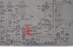
The schematic: https://www.dropbox.com/s/wi4egee2y...0mhz_readout_oscillosc ope_1988_sch.pdf?dl=0

Thanks in advance,
Mike
 

The symptoms suggest the HV to the CRT is oscillating or unstable. The overall size of the image depends on how much the X and Y plates can deflect the electron beam, as both axes are changing equally it suggests it isn't the voltage that creates the deflection changing but the time the electrons spend passing inside the deflection plates. If the HV drops, the electrons travel slower and hence spend more time between the plates which causes a magnified image.

The problem could be instability on the +12V supply line but as it feeds so many other parts of the circuit and they are not showing errors I would doubt that is it. More likely it is specific to the high voltage generator, my prime suspects would be C2008 then C2002 and then R2010. They are all inexpensive parts so given it's age it would be wise to replace them all. For C2008 use a part specified to have low ESR.


Brian.
 
Thanks Brian!

Will replace as suggested.

Just noticed that NE3001/NE3002 is flashing in sync with the screen flicker/zoom, and there's a subtle ticking sound in sync as well. I suppose that support your conclusion?

Again, many thanks!

Regards,
Mike
 

Flashing neons isn't going to create any problem but they could be an indicator of problems elsewhere. They are there as a crude over-voltage protection, when they flash they can discharge excessive voltage.

The ticking is more serious and could be the reason for the fault. Usually, the sound is caused by a flash-over of the HV to the CRT, what you hear is a spark. When the HV flashes over there will be a moment when the voltage drops and then recovers as the generator 'pumps it up' again. As it is repeating, it suggests the insulation is breaking down repeatedly at a voltage close to normal, it should be able to withstand substantially more.

The place to look is the tube base and the "High Tension Cord" from M1001 to the cap on the side of the CRT. Look in a darkened room to see if you can spot the spark. If it is around the cap on the CRT, with a grounded screwdriver (wire the shaft to the scope chassis) and obviously with the power off, peel the cap back and release the clip that connects it to the recess in the glass. It is likely to have some residual voltage on it, hence grounding the screwdriver. If the cap has any signs of streaking from the center clip to the edge, throw it away and get a new one, they can't be repaired. If it looks OK, clean it and the glass around it's mounting point with alcohol or similar solvent but avoid anything water based. Then when it is thoroughly dry, warm the cap (but not the CRT!) with a hair dryer until the plastic is pliable, it doesn't take much heat, then immediately fit it back to the CRT. The idea is that the plastic makes an air-tight bond to the glass as it cools down so moisture can't creep in again.

If you see sparking at the tube base, gently remove it and clean the pcb with solvent, the chances are moisture has made a layer of dust stick to it and it has become conductive. Removing the dust usually clears the problem as the base has lower voltages on it than the HV circuit.

The worst case scenario is M1001 has gone faulty as a replacement may be hard to find. It might be possible to build a new one as it will only contain a few diodes and capacitors but encapsulating it and mounting it may be difficult.

Brian.
 

Thanks again Brian,

- Checked C2008, C2002 capacitance (<±5%) and leakage (<1µA @30V), seem ok.
- R2010 within 1%.
- D2010 seem ok, Vf ~ 3.1V. D2011 not mounted.
- HV cap at the tube look good, the connector have no oxide or dark spots. Cleaned with IP and reseated. Thanks for the hair-dryer tip!
- Cleaned tube connector PCB with IP. It was not particularly dirty.
- No flashes visible. Checked along the high tension cord, the PCB/connector, the cap and inside the tube in a pitch black room.
- Found two possible cold soldered capacitors that was fixed, C331 and C332 (schema page 2, top right corner).

Observations (probes 10X, grounded in chassis);
+140V stable, no 100Hz ripple and about 5% ripple from the sparks (or whatever it is):
+5V shows about %20 ripple from sparks.
+12V have significant 100Hz ripple, and massive transients from the sparks:

12V-ripple.png

12V-flash.png

+16V (unfiltered rail) looks similar to +12V.

16V-ripple.png

I then checked PSU capacitors C1001, C1002 and C1010 for ESR (<1Ω) and capacitance (<±5%). Ripple could be due to high current draw i suppose. But can regulation be a factor? It does regulate though, it's pretty close to 12V and -12V on the rails.

A question; would there be any harm to disconnect +16V to the HV charge pump, i.e. P1003/CN2001? That would mean that everything is powered except the anode voltage if i read the schematic correctly. I'm curious if that would bring down the ripple on 12V to a sensible level, and hopefully isolate the problem to the anode voltage, if that is the culprit.

- - - Updated - - -

Correction: +5V has a horrible spikes from the sparks as well. Sorry!

5V-flash.png

- - - Updated - - -

Here's the +140V rail, which in fact is 160V.

160V.png

The schematic seem to mix 140V and 160V, not sure what is going on there.
 
Last edited:

It may help you to observe the chassis in a darkened room to spot any flashes or arcing.
 

It may help you to observe the chassis in a darkened room to spot any flashes or arcing.

Thanks E-design. I did and found nothing (as noted above). Could it be that the only flash/arcing that is going on is in fact the neon bulbs? When i looked again closely (dark room), i think i see arcing inside the neon bulbs at the very top of the rods.
 

Hello linux-dude,
Can you please refer to the picture below:

djh7Srt.jpg


Can you please check those high voltage caps for any damage, cracks or discoloration.

It would also help if you were to disconnect the ultor cap and check for any rust or
corrosion on the electrodes or in the hole that the electrodes enter. Also, clean the tube
where the ultor cap sits using isopropyl, but make sure you don't accidentally rub off any
of the conductive coating that's present on the bell of the tube.
You'll need to discharge the cap before removing it. Use a small insulated handled flat
screwdriver and connect a jumper lead from that to a good earth point, then gently
place the screwdriver underneath the cap to discharge it. It should then be safe to remove.
If you can, once inspected and/or cleaned, place some silicon grease under the cap to keep
it insulated, and prevent any sparks reaching the conductive coating.
Could you also please give us a part number of Q2001.
Please let us know how you get on.
Regards,
Relayer
 
Last edited:

During normal operation the two neon bulbs should be off. They are there as protection should a fault occurs, which forces the control grid to become too much positive in respect to the cathode. This can happen when there is a short or intermittent breakdown in the blanking/DC restorer circuit. This can cause an over current condition in the HV generator resulting in the hick-up-restart symptom shown in your video. If you see something looking like faint flyback lines, be more suspicious of the blanking/restorer section.

I would look at the HV caps in the restorer as well as the diodes which I marked. They often start leaking or breaking down in these circuits with age.

There is a similar section below it, which helps with auto-focus (focus correction with varying intensity settings). I don't think that is the culprit, but it may be worth checking the HV caps and diodes there as well if you don't find something in the first section.
 

Attachments

  • caps_diodes.jpg
    caps_diodes.jpg
    127.7 KB · Views: 141

i think i see arcing inside the neon bulbs at the very top of the rods

With use and years, I've seen neon bulbs start failing to light along the entire length of the rods. Or they flicker. I believe the gas loses its purity inside the bulb. THerefore its trigger voltage rises. Or the rods develop an insulating coating of some sort.

This effect is opposite to what you report. Anyway here's an interesting trick I have seen work: shine a light on the neon bulb. Impact of photons lowers its trigger voltage.

- - - Updated - - -

Even using a dim flashlight, it often causes a failing neon bulb to light brightly and continuously.
 
Status
Not open for further replies.

Similar threads

Part and Inventory Search

Welcome to EDABoard.com

Sponsor

Back
Top