searchforknowledge
Junior Member level 2
Sonnet standard and internal co-calibrated ports giving different results
Hi,
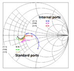
I am simulating the interconnection between four transistors as explained in the attached pdf file. The transistor is in the form of BEC (Base Emitter Collector). In the file you will find that I made a connection between the collector and emitter through a bridge like structure (Port2, Port3, Port4 and Port5). Under the bridge, there is a connection for the two bases (Port1, Port6, and Port7). I made two different simulations. In the first simulation, I assigned the port6 and port7 as co-calibrated internals ports with sonnet box as the ground plane. While in the second simulation, I extended the two ports (port6 and port7) in bringing them to the sonnet wall to make them standard ports and defined a proper reference plane to make it look similar to the first simulation. However, I got totally different results in both cases. I don't know which solution is correct and ideal for this type of problem. In the second case while de-embedding the reference plane, does the sonnet also remove coupling due to other ports for the required reference plane ?
Thanks a lot. View attachment Connections.pdf


