Continue to Site

Welcome to EDAboard.com

Welcome to our site! EDAboard.com is an international Electronics Discussion Forum focused on EDA software, circuits, schematics, books, theory, papers, asic, pld, 8051, DSP, Network, RF, Analog Design, PCB, Service Manuals... and a whole lot more! To participate you need to register. Registration is free. Click here to register now.

Several Warnings on Harmonic Balance simulation in co-simulation

Status
Not open for further replies.

rijubrata

Newbie level 5
Joined
Nov 3, 2015
Messages
10
Helped
0
Reputation
0
Reaction score
0
Trophy points
1,281
Activity points
1,427
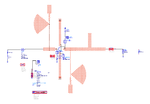
I am designing a FET based oscillator (fo = 6 GHZ) in ADS2014. I simulated the Bias Tee sections and output matching in momentum in 5 - 8 GHz frequency range. In momentum analysis, I am not getting warnings/errors other than internal port being changed from TML to NONE calibration.

After momentum analysis is over, I generate EM model and do co-simulation with FET using Harmonic Balance simulation.I used DC_Block and DC_Feed in the FET terminals accordingly.

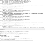
I cant understand from where I am getting the following list of warnings, would that mean the measured result will differ from the simulated one?

I have added the warnings and the picture of the circuit that I got in co-simulation
 

Attachments

  • Osc_ADS_cosim_warnings.png
    Osc_ADS_cosim_warnings.png
    42 KB · Views: 189
  • Osc_Warning_ADS.png
    Osc_Warning_ADS.png
    40.7 KB · Views: 141

Error Messages mean that the Frequency Response of the EM Simulated structure is narrower than all wide frequency response of the simulation set-up.
For instance, let say your VCO will work @ 10GHz and you assign 10 harmonics for this simulation setup.The frequency response of the EM Structure should cover upto-at least-100GHz to get a proper simulation otherwise ADS will extrapolate the frequency response of the EM structure up to max. frequency of the simulation set-up and this-probably- will be erroneously.

Thanks for explaining it beautifully.

Does that mean whenever I use harmonic balance simulator, I have to start from 0 GHz to maximum frequency that will be generated by HB simulator in the momentum analysis?

For this case, I am only interested to see if the oscillator is working on its design frequency with the amplitude I got from schematic. ADS will generate mesh at the highest frequency, so it will be very cpu hungry. I hope it won't give much changes at 6 GHz oscillation result that I already got from low range (5 - 8 GHz) of frequency simulation.


2. I have another doubt - when I am designing the FET footprint (the SMD chip having 4 pins with 2 sources) with 4 ports (TML ports by default) placed at the edges of the footprint in layout and run the momentum I get to see small changes in the S parameter results compared to without considering the microstrip footprint as it is considering the effects of the footprint parasitic. But, when those edge ports changed to internal ports due to connecting microstrip lines at those 4 ports, ADS momentum considers them as internal ports and doesn't consider the coupling effects among those 4 ports. How can I set the ports in momentum simulation to take care of the coupling effects / extra parasitics among those 4 ports?
 

Your oscillator is a highly nonlinear device, so it is NOT enough to only get the fundamental frequency right. The EM data must also be correct at DC (for bias and supply), and at least the first few harmonics.

Yes, EM is numbercrunching effort. But using EM with not enough bandwidth causes extrapolation, and that causes bad results. If you want to use EM, use it properly. Otherwise, you better use circuit simulation where the models are broadband by design. Your layout should be fine with microstrip circuit models, that will be better than extrapolated EM.
 

Thanks for explaining it beautifully.
Does that mean whenever I use harmonic balance simulator, I have to start from 0 GHz to maximum frequency that will be generated by HB simulator in the momentum analysis?
For this case, I am only interested to see if the oscillator is working on its design frequency with the amplitude I got from schematic. ADS will generate mesh at the highest frequency, so it will be very cpu hungry. I hope it won't give much changes at 6 GHz oscillation result that I already got from low range (5 - 8 GHz) of frequency simulation.

If you're interested in the oscillator is working or not working only, don't take these warnings into account.In fact, small signal s-parameter simulation using with OSC_Probe by cutting the loop will give you an insight about your oscillator conditions are satisfied or not.I suggest you to try first ( look at ADS examples ) to predict the fundamental oscillator operation.
But it's absolutely a must to start the EM simulation from DC if your layout carries DC current/voltages otherwise ADS may not converge.

Strange thing is that after setting the frequency range from DC in momentum simulation, I am still getting the warning in co-simulation
Warning detected by hpeesofsim during DC analysis `HB2

PADS =>
Error / Warning Info
WARNING : Transmission Line Port 3 modified to be an Internal Port, because a Transmission Line Port cannot be inside the circuit
WARNING : Because Port 3 is or became an Interior Port it will not be included in coupled mode calculations.
^^ Does that mean it will not take the coupling / parasitic effect among the 4 pins/ports?
 

I have simulated from 0 to 13 GHz covering DC and 2 harmonics (i.e 6 and 12GHz) in momentum, and got the following warning messages in Momentum.


(If I keep the upper frequency more than 16GHz, I am getting warning, so I kept only 2 harmonics in momentum)

"The size of the plus pin for S-parameter port 1 is electrically large above 15.8126 GHz, S-parameters may become unphysical."

INFO/WARNING/ERROR MESSAGE

Momentum MomEngine_64 11.20.082 (*) 2014.01 Feb 25 2014

Copyright 1992-2014, Agilent Technologies

Simulation Mode: uW

Substrate to be computed from 10 GHz to 13 GHz!

Using the minimal snap distance of 0.0004 mm

(4 layout resolution points) for layout healing.

Generating mesh at 13 GHz...

S-parameter simulation

--- WARNING -------------------------------------------------------------------


The 2D port solver data is not available for

thick conductor feedlines, using default values (50 Ohm)

for the transmission line parameters.


-------------------------------------------------------------------------------

Automatic selection: direct compressed matrix solver

Using multi-threading (4 threads)

Matrix size: 9458 (reduced: 9419)

--- WARNING -------------------------------------------------------------------


Frequency resolution of the adaptive frequency sampling algorithm is too small!

Cause : - non-smooth behavior of S-parameters.

: - reuse of earlier calculated S-parameter data.

Consider : - reducing size of frequency range.

- deactivating the file reuse option.


-------------------------------------------------------------------------------

The simulation results have been saved in dataset "_16.Integration_cosim_NEW__16copy__50ohm_MomUW".

STATUS MESSAGE

Adaptive: 100.0 % of frequency range covered

S-parameter simulation finished

Simulation finished on: Sat Dec 16 11:32:00 2017

Job finished on: Sat 16. Dec 11:32:11 2017

Exit status: Done

------------------------------------------------------------

I have deactivated "Reuse file from previous simulation" option in the momentum settings and kept Npts = 100 but still getting that warning.
 

"The size of the plus pin for S-parameter port 1 is electrically large above 15.8126 GHz, S-parameters may become unphysical." - To mitigate this issue, I added 0.05 mm x 0.05 mm stub in each of the port and did 0Hz to 32GHz simulation without this warning. This problem is solved now.

But I cant get away with that old warning which says ->

Frequency resolution of the adaptive frequency sampling algorithm is too small!

Cause : - non-smooth behavior of S-parameters.

: - reuse of earlier calculated S-parameter data.

Consider : - reducing size of frequency range.

- deactivating the file reuse option.


As I am designing a 10GHz oscillator so have to consider few harmonics. I tested 0 - 22GHz range, and landed with the same warning. As I need to test if any oscillation falls under that range, I have to sweep frequency instead of doing few single/adaptive ranges in Frequency Plan.
 

Status
Not open for further replies.

Part and Inventory Search

Welcome to EDABoard.com

Sponsor

Back
Top