Continue to Site

Welcome to EDAboard.com

Welcome to our site! EDAboard.com is an international Electronics Discussion Forum focused on EDA software, circuits, schematics, books, theory, papers, asic, pld, 8051, DSP, Network, RF, Analog Design, PCB, Service Manuals... and a whole lot more! To participate you need to register. Registration is free. Click here to register now.

Current drawn from the H bridge

Status
Not open for further replies.
Re: Commutation table using Hall sensors

As i first step i will read the hall sensor values and just switch the legs.

Right but Hall sensor outputs depend on the speed and the rotational speed depends on the applied power line frequency...

The Hall sensor output is the only way to actually ensure that the rotor is actually spinning as per the applied frequency. You slowly increase the frequency and ensure that the rotor is actually speeding up by looking at the Hall sensors.

Your approach is correct but you should try to sync with the transitions and not with the levels.
 

Re: Commutation table using Hall sensors

Your approach is correct but you should try to sync with the transitions and not with the levels.
I am trying to make sure that by configuring the hall sensor inputs to the input capture pins. So 3 channels for 3 hall sensor inputs. Whenever there is a transition i will get the interrupt and based on that trigger the legs. From the width of the pulse i will get frequency.
 

Hall sensors can provide both direction and speed; you should determine the speed from the time diff between two sensors and the direction from the sequence. Width of the pulse is not a reliable measure of the speed.
 
Able to toggle the debug LEDs every 1 second successfully. But while developing code using Hall Sensors confused with the following things


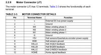
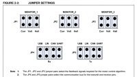
The hall signals are directly available in J7 connector and they are also available in the Monitor Jumper settings. Are they redundant in this case? In the monitor jumper settings in which place should I place the jumpers? They can be in any position or they have to be in Hall position?

2.


a. In the motor diagram for the Hall connector (P2) there is Vs, so i assume it is +5V and Vs(rtn) is Gnd. Is it correct? He did not specifically mentioned 5V.

b. I am currently not using but for the encoder connector (P3) a +5Vs is mentioned and +5Vs (rtn) is mentioned. So when i use both Hall and encoder do i need to short both the +5V pins and both the Gnd Pins?

c. In the P1 power connector there is FRAME GRND pin no 4. How do I use this pin? Do I need to Gnd it?

Please help.
 

In the motor diagram for the Hall connector (P2) there is Vs, so i assume it is +5V and Vs(rtn) is Gnd. Is it correct? He did not specifically mentioned 5V.
Yes, you guessed right.
I am currently not using but for the encoder connector (P3) a +5Vs is mentioned and +5Vs (rtn) is mentioned. So when i use both Hall and encoder do i need to short both the +5V pins and both the Gnd Pins?
Yes, they are independent and the same 5V and common ground should be used for both.
In the P1 power connector there is FRAME GRND pin no 4. How do I use this pin? Do I need to Gnd it?
It should be connected to the chassis body; it is not important for the circuit. It is designed to be connected to earth to prevent shock hazard (required in some countries) should not be left hanging...
 
The motor is running but i am driving at 100% duty. Is it ok? I do not know how to measure the performance of the system. What are the tools i require to do it? How to draw performance curve? How to do Torque control, I mean to say i want to generate some 1Nm Torque? Please help. Currently I do not have oscilloscope to attach the images. I am not sure if i can attach the video of motor spinning.
 

The problem i am facing is the motor gets heated in no time. Does it mean i can't run the motor for long time?
 

The problem i am facing is the motor gets heated in no time...

The only reason the motor gets heated is excessive current. You are perhaps driving the motor with square pulses instead of the recommended sine wave.

As the connections are now working, you need to put the sine table (as little as 8 pwm pulses per half cycle should be sufficient).

Also need to be seen whether you are correctly switching on the H bridge. If you use only positive pulses, the motor may run but shall cause overheating.

A simple test is using a lamp with sufficient power and correct voltage. The lamp should glow with full brightness if the H bridge switches are correct.

You can also use a diode in series with the lamp; the lamp brightness will be reduced to half with diode in either direction.

If both are fine, you will need a scope.
 
Thank you very much for the support. Yes i will try sinusoidal control using the following application note.
 

Attachments

  • 01017A.pdf
    313.9 KB · Views: 59

First try the Hall sensors using the protocol outlined in the same document. Once the Hall sensors are responding well, you move to the sine wave control. Once you implement the Hall sensor controls, the overheating will disappear (I hope).
 

I am driving the motor presently using block commutation 120 degrees switching but not able to acheive the required speed. Some advanced commutation like phase advance i want to implement but not sure how to do it. Can you please guide me how to implement phase advance to increase the speed?
 

Phase advance will be needed (very important) when you want to speed up to a high value (speed) rapidly. You make sure that you are getting required torque at the given speed. To increase the speed you will need higher frequency. But let me try to explain the basic idea of the phase advance - how to go from a lower speed to a higher speed (smoothly) without making the motor stall.

As you speed up, the torque will reduce and the current will increase. But as long as they are within the motor rating and capacity, these are not serious problems.

Let us say the your frequency is now f1; that means f1 cycles /sec. Each cycle will have 360 degrees and that will be made up of three 120 degree pulses applied to three windings.

In other words, each cycle will have 1/f1 secs and 1/3 the value for each phase. You want to increase the frequency to f2 in a smooth way- say a linear fashion.

The linear ramp will be done in a time domain; that is period for each cycle will be slowly reduced from 1/f1 to 1/f2. Let us say t1 = 1/f1 and t2 = 1/t2

This is done with a reasonable ramp rate; so we start t1, t1-dt, t1-2*dt, t1-3*dt, ... , t2.

Now you can calculate the phase values: each pulse gets narrower slowly. The motor speeds up in the same way.
 
I am not sure when i will have all clarifications cleared.
Q1. The phase advance does it apply for " 2 phase on" strategy or the square wave driving instead of sine wave driving?
Q2. For maximum torque the rotor flux should be at 90 degrees with respect to stator flux all the time? So for a "2 phase on" strategy it is not possible as rotor angle will vary from 60 to 90 degrees before the next hall change?
Q3. I created two commutation tables at different portions of the sine wave back emf signals. There was a difference in speed. Why is it so?
Q4. Finally most importantly for phase advance i switching the legs some microseconds before the hall change. Whether this is called phase advance? And why should the rotor speed increase in this case?
Sorry for lot of questions. But please help.
 

The phase advance does it apply for " 2 phase on" strategy or the square wave driving instead of sine wave driving?

The concept of phase is not meaningful with respect to a square wave; but we can relate to a phase by considering one full cycle (one period) and dividing it into 360 degrees. However, you should have no problem relating 0, 90, 180 and 270 degrees phase with respect to a square wave. Basically you are trying to increase the frequency and reducing the period slowly in a continuous manner by advancing the phase - by a little over a complete cycle- say you start one new cycle before the last one is over.

For maximum torque the rotor flux should be at 90 degrees with respect to stator flux all the time? So for a "2 phase on" strategy it is not possible as rotor angle will vary from 60 to 90 degrees before the next hall change?

We say that the fluxes should be about 90 offset between the stator and rotor fluxes in the steady state but you cannot hold that during acceleration or braking. But we have been talking about the PM motors so far...
 

Status
Not open for further replies.

Similar threads

Part and Inventory Search

Welcome to EDABoard.com

Sponsor

Back
Top