Continue to Site

Welcome to EDAboard.com

Welcome to our site! EDAboard.com is an international Electronics Discussion Forum focused on EDA software, circuits, schematics, books, theory, papers, asic, pld, 8051, DSP, Network, RF, Analog Design, PCB, Service Manuals... and a whole lot more! To participate you need to register. Registration is free. Click here to register now.

HF to HF transverter for all HF bands, will my idea work?

Status
Not open for further replies.

neazoi

Advanced Member level 6
Joined
Jan 5, 2008
Messages
4,119
Helped
13
Reputation
26
Reaction score
15
Trophy points
1,318
Location
Greece
Activity points
36,918
Hi, transverters usually transvert HF to V/U and/or microwave and vice versa.
However, I have a 10meter ssb transceiver and I would like to make a transverter to convert it to all HF bands.
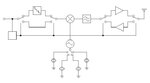
I attach the diagram of the transverter I intend to build and I would like to know if you can suggest any improvements on it.

It is shown in TX state and the difference of LO and RF is used. It works like this:

On RX. The signal from the antena passes to the wideband preamplifier, then to the LPF (used for TX mainly) and to the DBM, then finally ends on the 10m transceiver (which has it's own filters internally)

On TX. The signal outputs from the 10m transceiver then is attenuated to drive the DBM and mixed with single frequency band-switched local oscillator. Then the difference and the addition, pass through the LPF and only the difference is output it (it is a DBM and LO should be suppressed). Then the signal passes to the power amp and it is transmitted.

The input SSB signal on TX is detected by a circuit which changes the relays state from RX to TX. When not talking to the mike, the relays will be in the RX state, even if you have the transceiver PTT pressed, since the signal is SSB.

I have not included an output LPF because the power amplifier is balanced which helps minimizing harmonics, but also because the output level will be qrp 1-5W max.

Any ideas/improvements?
 

Attachments

  • Capture.JPG
    Capture.JPG
    25.3 KB · Views: 60

Should work but beware of the mixer frequencies. The problem with down-mixing like that is its difficult to filter the images and harmonics of the LO. You tend to get images falling into or received from other bands. If you do the math to find the crystal frequencies then look the mixer products from harmonics you will see what I mean. Also bear in mind the images will be very close to the desired frequencies so what you gain in simple concept may be lost in complex filtering.

Brian.


Here are the operating frequencies in MHz:

IN:28-29 LO:7 OUT:21-22
IN:28-29 LO:10 OUT:18-19
IN:28-29 LO:14 OUT:14-15
IN:28-29 LO:18 OUT:10-11
IN:28-29 LO:21 OUT:7-8
IN:28-29 LO:25 OUT:3-4
IN:28-29 LO:27 OUT:1-2

The mixer is a DBM (LO should be suppressed) and the difference is shown above, after the LPF (one for each band).
The LO used, has low harmonic content without the need for a filter, harmonics are lower than 50dBc.
Do you think this configuration with the above data should pose a problem?
 

Even with a DBM you will get stray signals unless you go to extreme measures to screen and filter them. Taking your examples:

IN:28-29 LO:7 OUT:21-22 3rd harmonic of 7MHz is 21MHz so it falls in the receiver range
IN:28-29 LO:10 OUT:18-19
IN:28-29 LO:14 OUT:14-15 LO itself is inside the receiver range
IN:28-29 LO:18 OUT:10-11
IN:28-29 LO:21 OUT:7-8
IN:28-29 LO:25 OUT:3-4
IN:28-29 LO:27 OUT:1-2

I'm ignoring direct images and those from LO harmonics.
This is why most systems use dual conversion process, the first mix it to a much higher frequency to make image rejection easier then the second mixer brings the result back to the frequency you want.

Brian.

The transceiver can do 28-29.7MHz, hm.. what if I start counting from 29MHz and use a LO 1MHz above instead for each band? The display KHz value would still reflect the transverted frequency value (so no need for calculations each time) but the LO and harmonics would not be in band.
Something like this

IN:29-29.7 LO:8 OUT:21-21.7
IN:29-29.7 LO:11 OUT:18-18.7
IN:29-29.7 LO:15 OUT:14-14.7
IN:29-29.7 LO:19 OUT:10-10.7
IN:29-29.7 LO:22 OUT:7-7.7
IN:29-29.7 LO:26 OUT:3-3.7
IN:29-29.7 LO:28 OUT:1-1.7 (out of band)

Is that better?
 

Status
Not open for further replies.

Part and Inventory Search

Welcome to EDABoard.com

Sponsor

Back
Top