Continue to Site

Welcome to EDAboard.com

Welcome to our site! EDAboard.com is an international Electronics Discussion Forum focused on EDA software, circuits, schematics, books, theory, papers, asic, pld, 8051, DSP, Network, RF, Analog Design, PCB, Service Manuals... and a whole lot more! To participate you need to register. Registration is free. Click here to register now.

Questions about driving MOSFET for current-measuring application

Status
Not open for further replies.

doncarlosalbatros

Full Member level 2
Joined
Nov 26, 2016
Messages
143
Helped
1
Reputation
2
Reaction score
1
Trophy points
18
Activity points
1,758
wySbA.png

This question is about a personal project and related to my previous question but focusing on different issues or questions. Heating wire is 1.9 ohm but I can adjust it to obtain 6A current pulse amplitude.

A uC's PWM output will control 2A to 6A current through a heating-wire and since the resistance might change, the current value roughly will be fed back to ADC of the uC for regulation ect. The circuit will be soldered on a perfboard.

I decided to use a single-supply op amp and low-side sensing to avoid common-mode-voltage related issues.

The freq. of the uC PWM is 500Hz and the PWM pulses are 0/5V . Here is the datasheet of the MOSFET: **broken link removed**


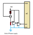
Here is how Im planning to wire it:
jd2.png

And here is the power dissipation of the MOSFET at %95 PWM(you can see the peak and average power):
jd3.png


I asked this to some and forums and some say I dont need any driver for the FET at this freq. and voltage.

My questions are do I need to worry about a driver for the MOSFET? Do I need heat.sink?

Is 50m Ohm resistor good for this application?

And what type of capacitors should I use for the active filter's 1uF caps?

If I go lower resistor than the input offset voltage becomes an issue. Is there a better rail-rail single supply opamp for a lower input offset voltage? I tried such in LTspice but getting worse results for the active filter.
 

Not sure which previous thread you are referring to, should give a link just in case. If it's related to shunt current measuring or PWM driver circuits, the new post should have been appended to the old thread.

A gate driver is suggested for fast MOSFET switching. Processor I/O pins aren't designed to drive multiple nF gate capacitance. Which gate driver impedance has been assumed in your switching loss simulation?

LM358 can be roughly considered a single supply OP. But the circuit requires the OP output to sink current through C6 at only mV output voltage, which isn't well managed by any single supply OP. The other question is what's the intended minimal measured current and current accuracy. OP offset voltage and output voltage range should be selected respectively. With LM358, the output voltage range towards negative rail might be improved by connecting a pull-down resistor in a 100 ohms range to the first stage output.

Thanks for your answer.

I meant this a totally different circuit. I don't want to use an inAmp only opAmps with single supply.

1-) "Which gate driver impedance has been assumed in your switching loss simulation?" Everything is in the schematics. I didn't get what you mean by this. But the PWM freq. is 500Hz %95 duty cycle in that simulation for the MOSFET power. The length of the heating-wire might vary so PWM will regulate the current. So PWM duty cycle will not be too smaller than 20% I guess.

I will use 5V pulses from Arduino Uno and Im confused whether I need a special driver like TC427 or a push-pull BJT driver for this application or maybe I dont need a driver at all. What do you suggest in this case?

2-) "LM358 can be roughly considered a single supply OP." I see less input offset error if I use rail-rail single supply LMC6482 instead of LM358 in simulation. Do you think LMC6482 is better for this application.

I can also provide some simulation plots if you want and if you do not use LTspice .
 

MCU_PWM_1 source isn't shown in the schematic, so it's reasonable to ask about the characteristic. If it's Arduino I/O, you should add something like 50 ohms port impedance in simulation. This will probably slightly increase switching losses, but I agree that operation at 500 Hz is possible without a dedicated gate driver. You should not reduce the gate series resistance considerably below 100 ohms, otherwise the ATmega maximum ratings might be exceeded.

A CMOS OP like LMC6482 has better sinking capability near the rails than LM358, offset error is however in a similar range.

I think I will use a gate driver even though I couldn't find a SPICE model. But to obtain better and less noisy results from the active filter with LMC6482 I was thinking to increase Rshunt a bit.

If I use a gate driver for the MOSFET do you think it is okay to use 200mOhm or 100mOhm for the Rsense(Rshunt) in the circuit I have in the question? What would you choose Rsense(Rshunt) roughly for this application where max current is 6A? Thanks.
 

I would rather use 50 mohm to reduce power dissipation, but it depends on your design preferences.
 

I would rather use 50 mohm to reduce power dissipation, but it depends on your design preferences.

FvM, Here is the final version:

jtr.png

FvM I really would like to have your comment on this final circuit before I solder on perfboard.

Here are changes:
I added a gate-driver for the MOSFET to be safe(but cannot simulate theres no model).
The supply for the heating-wire and MOSFET will be SMPS 24V(for a higher resistor) and the Vcc for ICs will be 12V.
Rsense will be 50mOhm
Opamp will be LMC6482A isntead of LM358
I added 100n decoupling caps to ICs and a 1u reservoir cap for the gate driver.
And finally R5, D2(4.7V zener) and C8 forms a ADC protection with anti-aliasing filter.

I would like to have your opinion about this final circuit before I solder.
1u caps for the active filter should be ceramic like X7R?

Thanks in advance.
 

Input B of the TC427 gate driver should be grounded, do not let it floating.

How did you choose the 10 ohms resistor for the gate driver ?
 

Input B of the TC427 gate driver should be grounded, do not let it floating.

How did you choose the 10 ohms resistor for the gate driver ?

Many thanks I will ground it!

10 Ohm is I saw in some example circuits. Shoulnt there be any resistor for the gate driver? Or what should be the value?

What do you think about the rest of the curcuit? I would appreciate your critics or suggestion.
 
Last edited:

Offhand I see no problem with your circuit.

If you wanted to save a little money you could use CD4050 buffer gates as a driver for the MOSFET.
You just tie all 6 inputs from one package together to the micro output and all the outputs in parallel to the MOSFET gate.
All the gates on one chip should switch sufficiently close together in time so there is no problem with tying their outputs in parallel.
Since your MOSFET is logic level, you can operate the CD4050 from 5V.
That should provide sufficient drive for the MOSFET at 500Hz.

crutschow Thanks for your answer. I dont want this circuit to draw more than 8A in case so Im planning to add a 8A fuse. And Im planning to use a 5W 50 mOhm resistor for current sensing. Here is what in my mind: https://uk.rs-online.com/web/p/through-hole-fixed-resistors/1249294/

But I read some places that I need to make Kelvin connection from this resistor to the active filter. Do you know what is meant by that in this context?
 

PWM is 500Hz.

I set active filter's cut off 20Hz to average the 500Hz PWM.

In my circuit for the active LPF filter I use R8=R9=8.2k and C6=C7=1uF. Instead if I use R8=R9=82k and C6=C7=0.1uF I get the same results.

I think it is difficult to find through hole 1uF stable cap .

In simulation if I use R8=R9=82k and C6=C7=0.1uF I get same results.

Which one better? Large caps(1uF) and low resistor(8.2k) or large resistor like 82k and low cap(0.1u)?

What type of capacitors is suitable for this application?
 

Hi,

Capacitor leakage makes timing vary, so general rule of thumb is that it's better to choose low value cap + larger value resistor than large cap + lower value resistor. It's easy to find PET (polyester/metallized film) 0.1uF through hole, as you know, these are - glossing over a few details - stable and recommended for timing applications. If you can find PPS through hole, even better - they are more stable over temp range (a quick search makes me wonder if they are available as through hole, you could check panasonic industrial and see if they still manufacture the 100nF one, digikey only came up with a 10nF/10,000pF through hole version).

PET are pretty good for what they cost, but bulky at 1uF, about 1cm*1cm*0.3cm. If you used a huge resistor, Polystyrene are also stable, but only available up to about 330pF, so the resistor would need to be several Mohms...

I don't recommend ceramic capacitors, others may differ, especially about NPO, which are tiny in comparison to PET.
 

Hi,

Timing or frequency precision is not important for your filterhere, because you are interested in the average value = about DC)
So distortion of the remaining ripple will not harm your signal.
Even if the resulting fc varies +/-20% won't harm your application.

The only thing you need to take care is leakage current.
--> here about any ceramics capacitor will do. Really no need for foil capacitors.

Klaus
 

Hi again,

Thanks for the answers until now. But I just noticed I have a big problem here.
Im measuring the current by this circuit. But my aim is to regulate the temperature of the nichrome wire where its length will vary.
I was planning to use PID control by adjusting the PWM current to a set value when the heating nichrome wire length is changed.
I was thinking the current is directly proportional to the temperature.

But in some forums it is written that one must measure both the current and the voltage across the nichrome wire to calculate the temperature.

1-) How can I measure the PWM voltage(almost 24V pulses) across the nichrome wire? It is above the MOSFET(CMV scares me). I need to measure it accurate and scale down for an 5V ADC :(

2-) Even I measure/monitor the resistance by R=V/I. How this R will let me to calculate the temperature? What is the formula?

3-) Instead of the method above is there an IC or a sensor like IR ect. which directly can measure the temperature of the nichrome wire?

Regards,
 

Hi,

It is impossible to calculate the temperature.
You may measure/calculate V, I, R, P, but not temperature.

Imagine you have 1m of your nichrome wire. One half of it is in free air, the other is in cold water.
Now that it is nichrome there is about no resistance change...so how do you think you can measure temperature?

Let's say it is a copper wire. Then it changes resistance with temperature. The higher the wire temperature, the higher the wire resistance. The problem with copper (and other metal) wire is, that it has PTC behaviour.
Therefore if one pice of wire is in cold water and the other in free air, then the hot piece of wire becomes higher resistance, and the cold wire becomes low resistance...and because of the series connection of both pieces of wire (same current) the voltage of the hot piece becomes higher and thus the heating power of the hot piece becomes higher. As a result...the hot piece becomes even hotter, the cold piece becomes even colder...usually not what you want.

Therefore it is recommended to use a wire with NTC characteristic. Like a carbon wire.
One technical example is to build a hot saw to cut polystyrene foam..

Klaus
 

The temperature along the wire will self-stabilize due to heat dissipation. There's no real problem of thermal runaway if the wire is operated in air with pure metal PTC characteristic and not at all with NiCr.

If you plan to determine the temperature by measuring resistance chance, you should be aware of the temperature coefficient of the material. NiCr 80/20 has only about 50 ppm/K t.c., not well suited for an accurate measurement. Better use pure metal wire which has much higher t.c.

If NiCr wire is set for your application, resistance measurement can still work for medium accurate temperature monitoring. µC's 10 bit ADC has probably not enough resolution for the purpose. You would want to make some calculations before defining the circuit.
 

Hello,

If I only regulate the average current when the wire length changes, would I at least get roughly similar temperatures?

Imagine a nichrome wire with length of L and passes 1,5A current and it heats to the temperature to T1 .
Now with the same wire if I halve its length to L/2 and pass again 1,5A current would it have a temperature close to T1?

I mean is the current measuring method/circuit I have been dealing can be used still to regulate the temperature roughly?
I came up with this table: http://hotwirefoamcutterinfo.com/_NiChromeData_files/1_Amperage.jpg
It related the temperature only with gauge not the length of it.
 

Hi,

If I only regulate the average current when the wire length changes, would I at least get roughly similar temperatures?
Yes.

Klaus
 

Status
Not open for further replies.

Similar threads

Part and Inventory Search

Welcome to EDABoard.com

Sponsor

Back
Top