Continue to Site

Welcome to EDAboard.com

Welcome to our site! EDAboard.com is an international Electronics Discussion Forum focused on EDA software, circuits, schematics, books, theory, papers, asic, pld, 8051, DSP, Network, RF, Analog Design, PCB, Service Manuals... and a whole lot more! To participate you need to register. Registration is free. Click here to register now.

UART softcore testbench

Status
Not open for further replies.

promach

Advanced Member level 4
Joined
Feb 22, 2016
Messages
1,199
Helped
2
Reputation
4
Reaction score
5
Trophy points
1,318
Activity points
11,636
I have completed UART Tx coding in verilog.

So far, I wish to test the UART transmission, but I am not quite sure how to test it.
What should I test for ?

I am not asking for testbench code. I need some general guidance regarding testing UART softcore.
Thanks!


Code Verilog - [expand]
1
2
3
4
5
6
7
8
9
10
11
12
13
14
15
16
17
18
19
20
module Tx_top(clk, reset, start, i_data, serial_out)   // UART transmitter :  parallel input, serial output
 
input clk;  // 48MHz
input reset;
input start;     // i_data is valid, so start transmission
input[7:0] i_data;
output serial_out;
 
wire baud_out;  // 9600bps baudrate clock
wire serial_data;  // output from serializer (TxUART)
 
TxUART tx (.clk(baud_out), .reset(reset), .start_tx(start), .i_data(i_data), .o_data(serial_data));
 
baud_generator bg (.clk(clk), .baud_out(baud_out));
 
shift_register sreg (.clk(baud_out), .reset(reset), .data_in(serial_data), .data_out(serial_out));
 
// FIFO tx_fifo (clk, reset, enqueue, dequeue, flush, i_value, almost_full, almost_empty, o_value);
 
endmodule


Code Verilog - [expand]
1
2
3
4
5
6
7
8
9
10
11
12
13
14
15
16
17
18
19
20
21
22
23
24
25
26
27
28
29
30
31
32
33
34
35
36
37
38
39
40
41
42
43
44
45
46
47
48
49
`define Tx_IDLE_BIT 0
`define Tx_START_BIT 1
`define Tx_DATA_BITS < `Tx_PARITY_BIT
`define Tx_PARITY_BIT 10
`define Tx_STOP_BIT 11
 
module TxUART(clk, reset, start_tx, i_data, o_data)
 
input clk, reset, start_tx;
input[7:0] i_data;
output reg o_data;
 
reg[3:0] state, next_state;
wire parity_bit;
 
always @(posedge clk)
begin
    if (reset) 
    state <= `Tx_IDLE_BIT;
    else 
    state <= next_state;
end
 
always @(*) 
begin : tx_fsm
    case(state)
    `Tx_IDLE_BIT    : next_state = (start_tx == 1) ?  Tx_START_BIT : `Tx_IDLE_BIT;
              o_data = 1;
 
    `Tx_START_BIT   : next_state = `Tx_DATA_BITS;
              o_data = 0;
 
    `Tx_DATA_BITS   : next_state = state + 1;
              o_data = i_data[state-2];
 
    `Tx_PARITY_BIT  : next_state = `Tx_STOP_BIT;
              o_data = parity_bit;
 
    `Tx_STOP_BIT    : next_state = `Tx_IDLE_BIT;
              o_data = 1;
 
    default         : next_state = `Tx_IDLE_BIT;
              o_data = 1;
    endcase
end
 
assign parity_bit = ^i_data; // even parity [url]http://www.asic-world.com/examples/verilog/parity.html[/url]
 
endmodule


Code Verilog - [expand]
1
2
3
4
5
6
7
8
9
10
11
12
13
14
15
16
// credit: Adapted from [url]http://zipcpu.com/blog/2017/06/02/generating-timing.html[/url]
 
module baud_generator(clk, baud_out)     // we are obtaining baud_out = 9600bps = clk/5000 where clk = 48MHz
 
input clk;
output baud_out;
 
wire ck_stb;
reg[15:0] counter = 0;
 
always @(posedge clk)
    {ck_stb, counter} <= counter + 13;  // (2^16)/5000 = 13.1
 
assign baud_out = ck_stb;
 
endmodule


Code Verilog - [expand]
1
2
3
4
5
6
7
8
9
10
11
12
13
14
15
16
17
18
19
20
21
22
23
24
25
// Credit: Adapted from [url]http://www.referencedesigner.com/tutorials/verilog/verilog_32.php[/url]
 
module shift_register(clk, reset, data_in, data_out)   // cascade of 10 registers
 
parameter N=10;
 
input wire clk, reset;
input wire data_in;
output wire data_out;
 
reg [N-1:0] r_reg;
wire [N-1:0] r_next;
 
always @(posedge clk)
begin
    if (reset)
    r_reg <= 0;
    else
    r_reg <= r_next;
end 
 
assign r_next = {data_in, r_reg[N-1:1]};
assign data_out = r_reg[0];     // Transmit LSB first
 
endmodule


Code Verilog - [expand]
1
2
3
4
5
6
7
8
9
10
11
12
13
14
15
16
17
18
19
20
21
22
23
24
25
26
27
28
29
30
31
32
33
34
35
36
37
38
39
40
41
42
43
44
45
46
47
48
49
50
51
// Adapted from [url]http://github.com/jbush001/NyuziProcessor/blob/master/hardware/core/sync_fifo.sv[/url]
 
module FIFO (clk, reset, enqueue, dequeue, flush, i_value, almost_full, almost_empty, o_value)
 
input clk, reset, enqueue, dequeue, flush, i_value;
output almost_full, almost_empty, o_value;
 
parameter SIZE = 22;
parameter ALMOST_FULL_THRESHOLD = SIZE;
parameter ALMOST_EMPTY_THRESHOLD = 1);
 
reg[4:0] head, tail, count;
 
assign almost_full = count >= ALMOST_FULL_THRESHOLD;
assign almost_empty = count <= ALMOST_EMPTY_THRESHOLD;
assign o_value = data[head];
 
always @(posedge clk) 
begin
    if (reset) begin
    head <= 0;
    tail <= 0;
    count <= 0;
    end
 
    else begin
    if (flush) begin
        head <= 0;
        tail <= 0;
        count <= 0;
    end
 
    else begin
        if (enqueue) begin
            tail <= tail + 1;
            data[tail] <= i_value;
        end
 
        if (dequeue) begin
            head <= head + 1;
        end
 
        if (enqueue && !dequeue)
            count <= count + 1;
        else if (dequeue && !enqueue)
            count <= count - 1;
    end
    end
end
 
endmodule


Usually one has a transmit and receive UART not just a transmit only...

In the testbench add a receiver UART so you can loop back transmit data and compare the received data matches the transmit data.

Or you can directly check the transmit protocol directly with a receiver bfm.
 

I have now finished UART transmitter hardware testing.
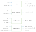
I am now planning on UART receiver overall block diagrams/ architecture.

If I wish to separate the repetitive Clock_Count hardware logic from the rx_state state machine into a separate verilog module, is it feasible and recommended ?

**broken link removed**
 

I am concerned if the block 'sample_data' is a bit large in terms of logic. Any suggestions or comments ?

UART_Rx_block_diagram.png
 

Why would it be large?

It's a simple serial to parallel conversion.
 

How should UART receiver hardware handles parity error ?

Just ignore it ?
 

Hi,

I think the UART receiver has to detect and repeort a priority error.
But how to handle it ... depends on the application. --> software

Klaus
 

How should UART receiver hardware handles parity error ?
In care the parity bit indicates an error, then generally the received byte is ignored. But as said in #7 it is upto the designer to decide.

Why is parity_value equal to value of 1 ?
I would suggest you to do some self reading on even parity and odd parity. https://en.wikipedia.org/wiki/Parity_bit
Before designing an UART one should know these things.
 

Why is parity_value equal to value of 1 ?
The code and waveform in your post don't match. The waveform has clk=0 so according to the code, parity_value and rx_error can't change.
What is
 

Status
Not open for further replies.

Part and Inventory Search

Welcome to EDABoard.com

Sponsor

Back
Top