Continue to Site

Welcome to EDAboard.com

Welcome to our site! EDAboard.com is an international Electronics Discussion Forum focused on EDA software, circuits, schematics, books, theory, papers, asic, pld, 8051, DSP, Network, RF, Analog Design, PCB, Service Manuals... and a whole lot more! To participate you need to register. Registration is free. Click here to register now.

Class problem help (Converter U-I)

Status
Not open for further replies.

rvijelie

Newbie level 3
Joined
Jun 5, 2017
Messages
3
Helped
0
Reputation
0
Reaction score
0
Trophy points
1
Activity points
36
Hello everyone, I have this problem where i need to propose the supply/input voltage and the output current (that I want to obtain) and then to calculate and choose the correct components so my circuit can work.
asd.png

So, I choose the supply to 5V and the output that i want to obtain to 20mA. From my calculations, I got R = 250ohms, and i choose it 270ohms (standard). But now, my teacher wants to calculate the values for the NPN transistor and choose one properly (I choosed bc107a, but i dont think it's good, because i didn't make any calculations). I also tried to do my best with the schematic in orcad.
asd2.png

Can i get a little help?
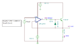
 

Hi,

If supply voltage = 5V, then it makes no sense that V_i = 5V, too.
V_i needs to be much smaller.

There are a lot of informations missing.
R_L range
I_L range
Opamp type..

And so on.

Klaus
 
The current through the emitter resistor is a function of the input voltage. Your supply voltage depends on the maximum load resistance. You can have a low input voltage and a low emitter resistor, or a high input voltage and a high input resistor. You need to pick some values and calculate the others.
 
The BJT is in saturation mode, Vbc>Vce.
The component values might be wrong
 

The BJT is in saturation mode, Vbc>Vce.
The component values might be wrong

VCC should be higher than Vin for normal operation otherwise because of Vin=I*R, there won't be any room for the transistor.
 
Did you notice that the output voltage of the opamp is higher than the supply voltage? Magic!
The collector of the transistor is doing almost nothing. The 270 ohm resistor is mostly powered by the base current of the transistor, instead of collector to emitter current.
Why do you think the current in R2 is almost nothing?
The opamp looks funny when it has no power supply.
 
Ok, so... I changed a lot of things. Now I'm confused about the Vi: doesn't matter what value i choose for Vi, the output of the opamp is the same (12v like his supply)..
Screenshot_1.png
 

Looks like you have 2 voltage supplies - both +12V & both at V+ and V- supply inputs of the opAmp - fighting with 21..22A against each other.
 

You will need to use an input voltage (Vref) that will give you the required current with the 270 Ohm resistor you selected.
 

Attachments

  • VCCS.png
    VCCS.png
    13.8 KB · Views: 135

Thanks a lot guys!!!
I got it now, so: i choosed my Vi=5V and the output current (Ie) that i wanted to obtain (≈20mA), because this circuit it's an U-I Converter. AND i got the Ie to 18.52mA, which is very ok and i'm happy.
Screenshot_1.png

Now i have calculate the VCE on the transistor (with formulas and stuff) and choose the correct transistor from the catalog (i put BC107a because it's the only transistor i know :roll:). Also, do you know what is the role of the diode in the whole circuit?
 

Hi,

You may use almost any standard PNP bjt .. it won't change much.

Diode:
I'd add a resistor between R1 and diode anode, maybe 10k.
Then the diode prevents from negative saturation of Opamp.

Klaus
 

I got it now, so: i choosed my Vi=5V and the output current (Ie) that i wanted to obtain (≈20mA), because this circuit it's an U-I Converter. AND i got the Ie to 18.52mA, which is very ok and i'm happy.
No, the emitter resistor is not the load. R2 is the load and its current is far from 20ma and is not controlled because the transistor is saturated.
 

Also, do you know what is the role of the diode in the whole circuit?[/B]

Since you are using a split supply which can enable the opamp to swing far enough negative under certain conditions, this can exceed the transistor's reverse b-e rating, which is normally around 5-7 V. The diode will limit the reverse voltage to about 0.7 V.
 

As already said the diode is used to avoid that negative voltages can reach the base of the transistor.

About the dimensioning, we can chose a transistor with a beta higher than 10, so Ic≈Ie. The equations are:

Vcc≈(R+RL)*Ic+Vce
since the op-amp is working in linear region, Vin=R*Ic that is "the voltage on the inverting input = the voltage on the non-inverting input"

Then substituting in the first formula Vcc≈Vin+RL*Ic+Vce

Let's suppose we want Ic=20 mA when Vin=1.3V.
Now we have to decide the maximum RL the regulator can operate under the wanted conditions. For example let choose RL(max)=1k. Finally we have to choose a Vce. For instance 2V that is far from Vce(sat). We obtain:

Vcc≈1.3+1k*20mA+2=23.3V

while R=Vi/Ic=1.3/20mA=65ohm
 

Status
Not open for further replies.

Part and Inventory Search

Welcome to EDABoard.com

Sponsor

Back
Top