David_
Advanced Member level 2
Hello.
I am designing a high-current buck-converter and if I could choose to use a interleaved design it would make a big difference, but I don't know anything about the feedback control och interleaved converters. Honestly I don't know much about ordinary feedback control, but I am going to develop an digital control loop and which ever sort of converter I choose learning is an integral part of the development procedure.
The availability of synchronous buck MOSFET gate drivers, especially with integrated MOSFETs makes interleaving very usefull. And given the effects on output ripple as well as heat management makes it almost an irresistible option, but I have tried to look for resources for learning about interleaved feedback control but I can't find anything.
I can't even find a clear description about how interleaved feedback control is structured or the basic idea of what is done.
On simplified schematics you can see that feedback looks the same as it does for single converters but that the feedback from the two converters in a 2-phase interleaved converter are routed together.
Which I don't understand, in my speculations I will assume that it relates to a 2-phase interleaved synchronous buck-converter.
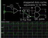
The PWM signal is shifted by 180 degrees, and the feedback information is collected and used to regulate the output. But how is it used?
Is the let''s say current compared and the two converters are regulated by not allowing ether one to exceed IOUT(max)/2?
I lost my train of thought so I'll continue later but any leads to any resources or any notes on this would be great appriciated.
Regards
