Continue to Site

Welcome to EDAboard.com

Welcome to our site! EDAboard.com is an international Electronics Discussion Forum focused on EDA software, circuits, schematics, books, theory, papers, asic, pld, 8051, DSP, Network, RF, Analog Design, PCB, Service Manuals... and a whole lot more! To participate you need to register. Registration is free. Click here to register now.

Arduino UNO unsure about coding for project, help appreciated!!

Status
Not open for further replies.
ok, i see where you are coming from now... alright i will try that, can i just take the 5v right from the arduino 5v pin to the A0?
Thank you.
 

Yes. Connect 6V pin of Arduino to A0 pin. If your dc modules inside arduino is already not damaged due to feeding more than 5V then you will get 50 as output on LCD if you use

current = analogRead(A0) * 50.0 / 1023.0

variable current is of type double.
 

so i verified that there was ~4.9 volts coming off of the 5v pin, and feed that into the arduino. Before i did that the lcd was reading like 3240 to 3350 amperes ???? has something to do with that conversion in the code i think. any way when i feed the 5 volts into A0 nothing changed it stayed around the 3240 to 3350 amperes, and i have no idea where its getting those numbers, how to you define something that when there is 0 it should read 0 is that possible?
 

Your arduino adc module is damaged. Try new arduino.
 

ok so i got it to work messing around with the code... one problem was order of operation in the code itself, another problem was /1023 was actually supposed to be 5/1023= dividing by 204.6.... the only thing i am unsure of now is when there is no input coming into the A0 the value jumps around from alot to like 1.5 amps, 3.5 amps, 1.4 amps, 3.3 amps... why is this? is there a code stating that if the A0 input is 0 then the output is 0?? incoming pictures of my latest success... :lol:

- - - Updated - - -

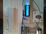
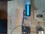
20170325_101238.jpg20170325_101645.jpg here are the two pictures i just took, one testing the 5V pin, the second testing the 3.3V pin .... SUCCESS!! , here is what i changed the code to: lcd.print(voltageinput/204.6)*50;

- - - Updated - - -

Thank you for you help and patience along the way, it was a great learning experience for me... if you have any suggestions on how i can fix my last issue of how to get the value displayed to stop jumping around so much when there is no input that was be so great!!, its only when there is no input when i had the 5v and 3.3v going into A0 the value didnt move at all

- - - Updated - - -

one conclusion i have is to set the delay to (100) instead of 1000, then you cant actually tell what value its reading and it looks like its searching for a value to read and then when i put the 5 volts or 3.3volts in it displays that instantly and doesnt move..... but i feel there is a better way to do this where it will display 0 and stay there until an input is detected
 

I will send you adc reading example project. Did you check analog read example in Arduino IDE ?
 

digitalWrite(A0, INPUT_PULLUP); // set pullup on analog pin 0 is this the code i am looking for to stop the no input value from "floating" to random values?
 

I am not sure about it. I have never used such a code. I have done practical adc reading using arduino and it gives me correct values. It gives 0V = 0 and 5V = 1023 raw adc value.

I already told you

Code:
analogRead(A0) * 5 / 1023
will give 0 to 5 value

and [analogRead(A0) * 50 / 1023[/code] will give a value between 0 and 50

because adc resolution is 10 bit which is equal to 1023.

Between successive analog reads a small delay has to be used. say 1ms.
 

im aware of all of these, i believe you missed my question, my only issue is to get the displayed value from jumping all over the place when there is no input ( no voltage going into) on A0, it jumps from like 0.0 to 17.5 to 49.9 and back down repeatly

- - - Updated - - -

i have come across an article saying that because when theres no input the value "floats" around and to stop this put a pull down resistor in series with the pin
 

solved this by the way, it was because i didnt have the arduino grounded to my sensing circuit, when i connected the A0 pin to the diode side of the resistor, and the digital ground to the grounded side of the resistor the value stayed at 0 until voltage was detected then it worked extremely accurately. 1V=10amp display 5 volt = 50 amp display.
 

Status
Not open for further replies.

Part and Inventory Search

Welcome to EDABoard.com

Sponsor

Back
Top