Continue to Site

Welcome to EDAboard.com

Welcome to our site! EDAboard.com is an international Electronics Discussion Forum focused on EDA software, circuits, schematics, books, theory, papers, asic, pld, 8051, DSP, Network, RF, Analog Design, PCB, Service Manuals... and a whole lot more! To participate you need to register. Registration is free. Click here to register now.

EMC and Power Factor regulations for big companies

Status
Not open for further replies.
T

treez

Guest
Is it true that big companies, who pay for their reactive power draw, can have SMPS's connected to the mains with any low power factor they want, and draw any amplitude of mains harmonics that they want?
 

Power Factors below .80-.85 are charged penalty fees by the utility company because they are drawing more current than they are actually using. Local government will conduct regular PFC audit in many countries.
For power factor correction two methods are their Active PFC (SMPS Based) and Passive PFC(Capacities/Inductive)

It is easy to implement active PFC stage in SMPS, Motor drive …ect but for a direct driven induction motors similar parts required passive PFC stage. In passive method for inductive load capacitor bank is the passive PFC components and for capacities load conductors are the passive PFC components
Refer
https://www.westek.com.au/wp-content/uploads/2014/06/PFC-Systems-Catalogue.pdf
 
  • Like
Reactions: treez

    T

    Points: 2
    Helpful Answer Positive Rating
Thanks, but i just wonder if the government really cares about power factor......as long as people pay for their poor power factor.....i mean, there are 100's of millions of <75w smps at work in uk with no pfc.......and you dont hear about the electricity supply system overloading due to it.
 
Last edited by a moderator:

Perhaps because it could be easiest to manage PFC on the average and predictable power consumption pattern of a mass consumer profile within a spread grid if compared to a punctual site on which just turning on/off determined process will add substantial harmonics at some local part of the utility system.
 

Thanks, but i just wonder if the government really cares about power factor......as long as people pay for their poor power factor.....i mean, there are 100's of millions of <75w smps at work in uk with no pfc.......and you dont hear about the electricity supply system overloading due to it.

Government should be care about it because it will leads to less voltage(Voltage drop) in the distribution system, Suppose you have a 1KW electric motor(115V@60Hz) and you got permission for 1KW(115V@ 8.7A) usage from government. If your motor PF is 0.8 then your motor will consume 1.2KW(115V@10.4A) power from the distribution system. So the distribution system will over ride if the distribution system not consider more power.

PFC is applicable only for inductive loads(Motor, induction heating ..ect) and capacities load (Battery charging, LED bulbs). For resistive load PFC will be always 1
Supply system will not overload when the system considered 1.5times the required power!!!!!
 

Suppose you have a 1KW electric motor(115V@60Hz) and you got permission for 1KW(115V@ 8.7A) usage from government. If your motor PF is 0.8 then your motor will consume 1.2KW(115V@10.4A) power from the distribution system.

yes but as you know, that extra 200W is not actually "consumed" as it represents reactive power......the only extra dissipation it creates is due to its i^2R loss in the conductors of the mains power system.
 

Well reactive power dissipate as I^2R loss

There was a correction in your post:
As per calculation in my earlier post #5 the excess current of 10.4A (due to poor PFC) will dissipate as I^2R loss on motor wingdings and motor cables

This dissipation will considered as an additional loss.
 

As per calculation in my earlier post #5 the excess current of 10.4A (due to poor PFC) will dissipate as I^2R loss on motor wingdings and motor cables
Thanks thats interesting, and are you saying that if a power factor corrector were upstream of the motor, then that extra dissipation in the motor cables and motor windings would not happen?
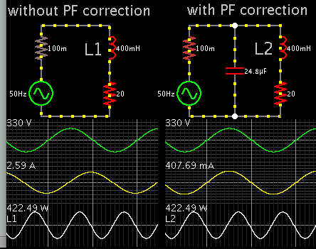
 

Thanks thats interesting, and are you saying that if a power factor corrector were upstream of the motor, then that extra dissipation in the motor cables and motor windings would not happen?

5519489900_1490070623.png


This simulation told me a lot about power factor error and correction. The load is mostly inductive. Notice the scope trace which shows it drawing current at the wrong time in the cycle, thus it draws excessive current. Power factor is hampered.

The problem is corrected by adding a carefully chosen value of capacitor upstream of the load. Supply voltage and Ampere waveforms are aligned.

Notice both loads carry the same wattage, but the corrected circuit carries much less Amperes.
 
Thanks thats interesting, and are you saying that if a power factor corrector were upstream of the motor, then that extra dissipation in the motor cables and motor windings would not happen?

Excess current (reactive current) due to poor PFC will dissipate all the current path which include motor winding, Motor cable and transmission line.
Post #9 will be a self explanation

Refer
https://www.progress-energy.com/assets/www/docs/business/power-factor-how-effects-bill.pdf
 
  • Like
Reactions: treez

    T

    Points: 2
    Helpful Answer Positive Rating
Hi,

Every winding current will cause heat in the windings.

But on the other hand a compensation capacitor won't change motor winding current.
Solely the grid current will be improved.

So the compensation doesn't change motor winding power dissipation.

But it reduces grid loss: in generator, wires, transformers..

Klaus
 
  • Like
Reactions: treez

    T

    Points: 2
    Helpful Answer Positive Rating
Status
Not open for further replies.

Part and Inventory Search

Welcome to EDABoard.com

Sponsor

Back
Top