David_
Advanced Member level 2
Hello.
I have been thinking about making my own SMU like device(Source Measure Unit) and for that I need to take a signal from an op-amp and boost the current capability a huge amount. This isn't a new problem for me though since from very early in my electronics interest I have wanted a power amplifier to be put at the output of my arbitrary function generator, but the best I could come up with was a unity-gain follower using an BUF634 - 250-mA High-Speed Buffer which was considering my experience with electronics at that time a smashing success but I was then as now not happy about ±250mA.
But today I am thinking about an SMU circuit which should be capable of supplying maximum ±5V @ ±1A, but this thread is just as much about the creation of an similar circuit that can output far higher currents, something like ±5A.
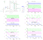
I have found a solution for boosting the current up to ±5A with the following circuit(all the pictures of waveforms that I might put in this post later will all have been generated with this simulation):

The circuit can manage a load of 0.85Ω at 10Vp-p up to 100kHz(but at higher currents there are bumps around the zero-crossing which I beilive has to do with the...don't know what it's called but has to do with the transistors 0,6V drop), any lower load/higher current will produce clipping of the negative part of the waveform and below 0,2Ω the positive part of the waveform starts to clip as well.
I have neglected to use the two resistors following each Darlington collector that was included in the original schematic that I found somewhere because they caused some weird behaviour that I didn't understand. The first problem with this circuit is that it is completely unprotected(those missing resistors was said to be some small measure of over current protection)and I don't know how to fix that but the even bigger problem is it's inability to manage any capacitance placed across the buffers output and 0V/GND. And I want my SMU circuit to be able to handle a lot of capacitance but I have no idea of how to do that.
The SMU circuit would be able to output DC or any waveform you'd like but probably most often sinewaves.
Look what happens if I add 10nF at the buffers output:

or 0,1µF:

The waveform looks similar as the picture above with increasing capacitances until it looks more like this next picture which is made with 47µF at the output:

The last picture which is attached but not shown is a picture of the bumps around the zero-crossing.
So, why is this?
And more importantly what can I do about it?
I tried inserting a small resistor in the path of the output which seems to calm it down but it feels as an inappropriate place for a resistor.
And what is up with the frequency of the oscillations?
It seems to decrease with increasing capacitance, but what other parts of the circuit is it that is causing this?
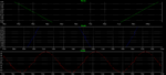
I would want a buffer that can output 100kHz and not mind being loaded with 10µF, but look at this picture of a 10kHz and a 100kHz sinewave while they are loaded by 10µF:

Any and all advice would be greatly appreciated.
Regards
- - - Updated - - -
Using an op-amp which is rated for a much higher load capacitance than the one used in the simulations that was shown in my first post did decrease the problem but it's a long way from being gone.
Is it impossible to use an op-amp in an application like this?
I have been thinking about making my own SMU like device(Source Measure Unit) and for that I need to take a signal from an op-amp and boost the current capability a huge amount. This isn't a new problem for me though since from very early in my electronics interest I have wanted a power amplifier to be put at the output of my arbitrary function generator, but the best I could come up with was a unity-gain follower using an BUF634 - 250-mA High-Speed Buffer which was considering my experience with electronics at that time a smashing success but I was then as now not happy about ±250mA.
But today I am thinking about an SMU circuit which should be capable of supplying maximum ±5V @ ±1A, but this thread is just as much about the creation of an similar circuit that can output far higher currents, something like ±5A.
I have found a solution for boosting the current up to ±5A with the following circuit(all the pictures of waveforms that I might put in this post later will all have been generated with this simulation):
The circuit can manage a load of 0.85Ω at 10Vp-p up to 100kHz(but at higher currents there are bumps around the zero-crossing which I beilive has to do with the...don't know what it's called but has to do with the transistors 0,6V drop), any lower load/higher current will produce clipping of the negative part of the waveform and below 0,2Ω the positive part of the waveform starts to clip as well.
I have neglected to use the two resistors following each Darlington collector that was included in the original schematic that I found somewhere because they caused some weird behaviour that I didn't understand. The first problem with this circuit is that it is completely unprotected(those missing resistors was said to be some small measure of over current protection)and I don't know how to fix that but the even bigger problem is it's inability to manage any capacitance placed across the buffers output and 0V/GND. And I want my SMU circuit to be able to handle a lot of capacitance but I have no idea of how to do that.
The SMU circuit would be able to output DC or any waveform you'd like but probably most often sinewaves.
Look what happens if I add 10nF at the buffers output:
or 0,1µF:
The waveform looks similar as the picture above with increasing capacitances until it looks more like this next picture which is made with 47µF at the output:
The last picture which is attached but not shown is a picture of the bumps around the zero-crossing.
So, why is this?
And more importantly what can I do about it?
I tried inserting a small resistor in the path of the output which seems to calm it down but it feels as an inappropriate place for a resistor.
And what is up with the frequency of the oscillations?
It seems to decrease with increasing capacitance, but what other parts of the circuit is it that is causing this?
I would want a buffer that can output 100kHz and not mind being loaded with 10µF, but look at this picture of a 10kHz and a 100kHz sinewave while they are loaded by 10µF:
Any and all advice would be greatly appreciated.
Regards
- - - Updated - - -
Using an op-amp which is rated for a much higher load capacitance than the one used in the simulations that was shown in my first post did decrease the problem but it's a long way from being gone.
Is it impossible to use an op-amp in an application like this?