Continue to Site

Welcome to EDAboard.com

Welcome to our site! EDAboard.com is an international Electronics Discussion Forum focused on EDA software, circuits, schematics, books, theory, papers, asic, pld, 8051, DSP, Network, RF, Analog Design, PCB, Service Manuals... and a whole lot more! To participate you need to register. Registration is free. Click here to register now.

SSB generadion and reception using simple phasing mixers

Status
Not open for further replies.

neazoi

Advanced Member level 6
Joined
Jan 5, 2008
Messages
4,122
Helped
13
Reputation
26
Reaction score
15
Trophy points
1,318
Location
Greece
Activity points
36,951
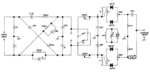
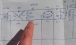
Hi I have found these two ssb modulators/demodulators.
The first does not use an audio transformer, whereas the second does.
Note that the second requires a LO phase splitting transformer as well.

However the first one, if used as a demodulator, will present a big resistange to the demodulated audio, due to the 5K pots and the 5.5k resistors.

Won't it?

So I guess it is not good as a demodulator because of the big loss of the audio signal due to these resistors?
 

Attachments

  • 1.PNG
    1.PNG
    47.6 KB · Views: 111
  • 2.PNG
    2.PNG
    788 KB · Views: 112

There is no need for the +-90* phase shifting when summing the audio.
SSB modulation does need 90° phase shift of audio and carrier, also demodulation if reception of the other sideband shall be suppressed.
 
  • Like
Reactions: neazoi

    neazoi

    Points: 2
    Helpful Answer Positive Rating
SSB modulation does need 90° phase shift of audio and carrier, also demodulation if reception of the other sideband shall be suppressed.
Thanks for confirming what I knew was correct.

The basic question is: "However the first circuit of post #1, if used as a demodulator, will present a big resistange to the demodulated audio, due to the 5K pots and the 5.5k resistors. Won't it?

If so there will be huge recovered signal loss
 

Problem is the low impedance and asymmetrical termination, it's simply not designed as demodulator.
 
  • Like
Reactions: neazoi

    neazoi

    Points: 2
    Helpful Answer Positive Rating
The SSB modulator from the left is from the issue April 1973 of Ham Radio Magazine.
It has very poor side band rejection (< 20dB) and because is using single balanced mixers also the carrier rejection is not impressive.
Even the author of the article mention that the side band rejection is not great, and the audio balance adjustment is very difficult on this circuit.
Using a double balanced DSB modulator, and the cheapest ladder crystal filter that you can get, you obtain at least 40dB side band rejection.
 
  • Like
Reactions: neazoi

    neazoi

    Points: 2
    Helpful Answer Positive Rating
Problem is the low impedance and asymmetrical termination, it's simply not designed as demodulator.

Whereas I see that the circuit on the right is suited as a demodulator as well, is that right?

- - - Updated - - -

Using a double balanced DSB modulator, and the cheapest ladder crystal filter that you can get, you obtain at least 40dB side band rejection.
Yes I know, but it will be a single frequency if direct conversion, else dual conversion must be used. I am looking for a simple circuit even if sideband and carrier suppression is not too good. 20db or so is better than no suppression at all.
 

The situation is rather different between a modulator for transmission, and demodulator for reception.
For transmission the amplitude is fairly constant, but you need as good carrier and opposite side band suppression as you can get. Problems of noise or overload are never going to occur.

For reception, just about the opposite is true. There needs to be good dynamic range with as little noise as possible, and perfect carrier suppression becomes much less important.

You talk about TX SSB where audio has been previously compressed, that is why you refer that amplitude is almost constant on TX. But for simple circuits without compression this is not true. I agree about the other things you mention.

However, the question I want to solve is that, why the first circuit is worst than the second, for reception (if it is). Can anyone suggest why?

Post #5 says about low impedance and asymetrical termination, but why is that? I thought the high values of the audio series pots were the problem.
Does the second circuit eliminate these problems?
 

Unless you are broadcasting full dynamic range classical music on SSB, I would hope that you are at least running some kind of ALC, and that you are monitoring your amplitude, even if its only an occasional glance at the PA current.

That is all it takes to keep the amplitudes right through the whole transmission chain within fairly close limits.
 

Status
Not open for further replies.

Part and Inventory Search

Welcome to EDABoard.com

Sponsor

Back
Top