Continue to Site

Welcome to EDAboard.com

Welcome to our site! EDAboard.com is an international Electronics Discussion Forum focused on EDA software, circuits, schematics, books, theory, papers, asic, pld, 8051, DSP, Network, RF, Analog Design, PCB, Service Manuals... and a whole lot more! To participate you need to register. Registration is free. Click here to register now.

"Less than 2 connections at node" error message in pspice

Status
Not open for further replies.

msmol

Junior Member level 1
Joined
Jun 9, 2015
Messages
15
Helped
0
Reputation
0
Reaction score
0
Trophy points
1
Activity points
168
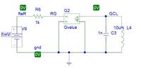
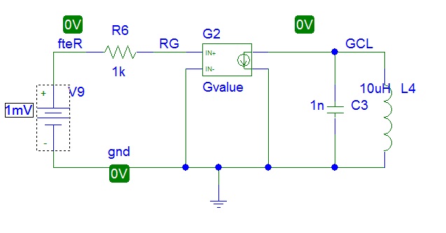
Hi everybody. I have redesign a scheme I was using and was very successful. But when I tried to simulate a DC sweep, I got this error message (Pspice 9, student version):


Code dot - [expand]
1
2
3
4
5
6
7
8
9
10
11
12
13
14
15
16
17
18
19
20
21
22
23
24
25
26
27
28
29
30
31
32
33
34
35
36
37
38
39
40
41
42
43
44
45
46
47
48
49
50
51
52
53
54
55
56
57
58
59
60
61
62
63
64
65
**** 01/14/16 12:47:12 *********** Evaluation PSpice (Nov 1999) **************
 
 * C:\Program Files\OrCAD_Demo\PSpice\Diodo MT 2.sch
 
 
 ****     CIRCUIT DESCRIPTION
 
 
******************************************************************************


* Schematics Version 9.1 - Web Update 1
* Thu Jan 14 12:47:12 2016


** Analysis setup **
.DC LIN V_V9 -0.04 0.04 0.00001 
.OP 
 
 
* From [PSPICE NETLIST] section of pspiceev.ini:
.lib "nom.lib"
 
.INC "Diodo MT 2.net"
 
**** INCLUDING "Diodo MT 2.net" ****
* Schematics Netlist *


L_L4         GCL 0  10uH  
C_C3         GCL 0  1n  
G_G2         GCL 0 VALUE { V(RG, 0) }
R_R6         fteR RG  1k  
V_V9         fteR 0 1mV
 
**** RESUMING "Diodo MT 2.cir" ****
.INC "Diodo MT 2.als"


**** INCLUDING "Diodo MT 2.als" ****
* Schematics Aliases *
 
.ALIASES
L_L4            L4(1=GCL 2=0 )
C_C3            C3(1=GCL 2=0 )
G_G2            G2(OUT+=GCL OUT-=0 IN+=RG IN-=0 )
R_R6            R6(1=fteR 2=RG )
V_V9            V9(+=fteR -=0 )
_    _(GCL=GCL)
_    _(gnd=0)
_    _(RG=RG)
_    _(fteR=fteR)
.ENDALIASES
 
 
**** RESUMING "Diodo MT 2.cir" ****
.probe
 
 
.END


ERROR -- Less than 2 connections at node RG

I attach an image of the scheme, so you can see the node names.

Thanks in advance.

M.

 
Last edited by a moderator:

Most easily achieved by omitting useless R6. Otherwise must connect a dummy resistor from RG node to ground, e.g. Gohm value.
 

Most easily achieved by omitting useless R6. Otherwise must connect a dummy resistor from RG node to ground, e.g. Gohm value.

What do you mean with ommiting? Because I checked the netlist and all the parts are present.
 

You've written wrong expression for GVALUE.
Change it from { V(RG, 0) } to { V(RG) }
If you need a differential of input pins then write as { V(RG)-V(net2) }, V(net2) is zero in your circuit configuration.
 
  • Like
Reactions: msmol

    msmol

    Points: 2
    Helpful Answer Positive Rating
You've written wrong expression for GVALUE.
Change it from { V(RG, 0) } to { V(RG) }
If you need a differential of input pins then write as { V(RG)-V(net2) }, V(net2) is zero in your circuit configuration.
The shown net list is automatically generated by PSPICE and hasn't been written by msmol. it's just the translated schematic entry.
Because I checked the netlist and all the parts are present.
And RG is a node with single connection, as the net list shows. The problem is that the G2 input is not loading the node, just sensing the voltage. For the same reason R6 is useless. I suggested two possible solutions. It could make sense to try it even if you don't understand why.
 
  • Like
Reactions: msmol

    msmol

    Points: 2
    Helpful Answer Positive Rating
Looks like "msmol" made some mistake on GVALUE part due to which the wrong netlist getting written.
I checked at my end, it is written as below by tool. And it works fine.
G_G2 GCL 0 VALUE { V(RG, 0) }

I am using 16.6 version though.
-------------------------------------------------------------------------------------

Sorry for the above confusion.

@msmol -- I checked your netlist as it is. And it is working fine at my end. I am using 16.6 version.
 
Last edited:

You've written wrong expression for GVALUE.
Change it from { V(RG, 0) } to { V(RG) }
If you need a differential of input pins then write as { V(RG)-V(net2) }, V(net2) is zero in your circuit configuration.

I rewrited the netlist as follows:

Code:
Diodo MT 3
V_V8         inR2 0 30mV
R_R2         inR2 RG  1g  
G_G1         GLC 0 VALUE { PWR((COS(5000*V(RG)-5)-COS(5000*V(RG)-40)),2)*(V(RG)*0.8e-8) }
L_L3         GLC 0  6e-5  
C_C3         GLC 0  1e5
.END

But I keep getting the same error message.

Most easily achieved by omitting useless R6. Otherwise must connect a dummy resistor from RG node to ground, e.g. Gohm value.

This solution effectively helped to jump over the problem, but for the work I need to do, it would be better not to add parts, just to keep this equivalent circuit as simple as possible.

Thanks "FvM" and "mvaseem", I hope I can solve it with the recoding option. Nevertheless, If you can keep helping me, it will be so useful.
 

Status
Not open for further replies.

Part and Inventory Search

Welcome to EDABoard.com

Sponsor

Back
Top