Continue to Site

Welcome to EDAboard.com

Welcome to our site! EDAboard.com is an international Electronics Discussion Forum focused on EDA software, circuits, schematics, books, theory, papers, asic, pld, 8051, DSP, Network, RF, Analog Design, PCB, Service Manuals... and a whole lot more! To participate you need to register. Registration is free. Click here to register now.

How do you design a voltage controlled variable resistor for low voltages?

Status
Not open for further replies.

vineel13

Newbie level 6
Joined
Aug 12, 2015
Messages
14
Helped
0
Reputation
0
Reaction score
0
Trophy points
1
Activity points
127
Well I am aware that voltage controlled resistors can be designed using MOS transistors, but these devices would only work if they are operated in their ohmic/linear region. But suppose if I still want to get a linear change in resistance even below the cutoff/threshold voltage (0.6-0.7 V),
is there any mechanism or other circuitry which can be used to achieve this ?

Thank You.
 

Depends on power dissipation in the variable resistor. You can use photoresistors for a milliwatt level, using a LED or bulb as light source.
For high power there is a good solution in thermally varied resistive wires (a coil), heated by a variable heater.

Linearity is a challenge, you will have to linearize the driver.
 

I still want to get a linear change in resistance even below the cutoff/threshold voltage (0.6-0.7 V), is there any mechanism or other circuitry which can be used to achieve this ?

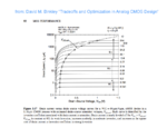
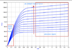
The resistive part of the Ids vs. Vds characteristic (called triode or linear region) has nothing to do with the MOSFET's threshold voltage, but starts well below its saturation voltage VDS,sat down to 0 volts, s. the foll. image:
Id_regions.png .

In weak inversion operation (deep subthreshold) the saturation voltage can go down well below 200mV, down to a minimum of ≈ 4Vt ≈ 100mV (@ 25°C), comp. this image:
Binkley__saturation_voltage_p92.png .

So in such case your resistive range would be between zero and several tens of milliVolts.
 

You just need mos with extremely low VT, check and see if your process offers native mos transistors.
 

Rheostat and servo motor.
 

Well as far as what i see is when i used a 180nm NMOS till around 0.6-0.7 there has been a linear change but when I go below it it starts dropping very very quickly and finally becomes zero.
 

... when I go below it it starts dropping very very quickly and finally becomes zero.

No: in this linear region the resistance is (nearly) constant: R=ΔVds/ΔIds , down to a DC voltage of 0 volts, and this resistance is still valid for small voltages in the negative range; means a superimposed ac signal of a few tens to even hundreds of milliVolts sees exactly this resistance, even if the DC voltage is zero.

However you can change this resistance via Vgs. See the triode or linear called region in the 1st image in my above post.
 

Status
Not open for further replies.

Part and Inventory Search

Welcome to EDABoard.com

Sponsor

Back
Top