Continue to Site

Welcome to EDAboard.com

Welcome to our site! EDAboard.com is an international Electronics Discussion Forum focused on EDA software, circuits, schematics, books, theory, papers, asic, pld, 8051, DSP, Network, RF, Analog Design, PCB, Service Manuals... and a whole lot more! To participate you need to register. Registration is free. Click here to register now.

[SOLVED] 900 MHz collpits oscillator

Status
Not open for further replies.

farzaneh_2561

Member level 1
Joined
Jul 8, 2013
Messages
34
Helped
1
Reputation
2
Reaction score
0
Trophy points
6
Activity points
248
Hi RF Experts,
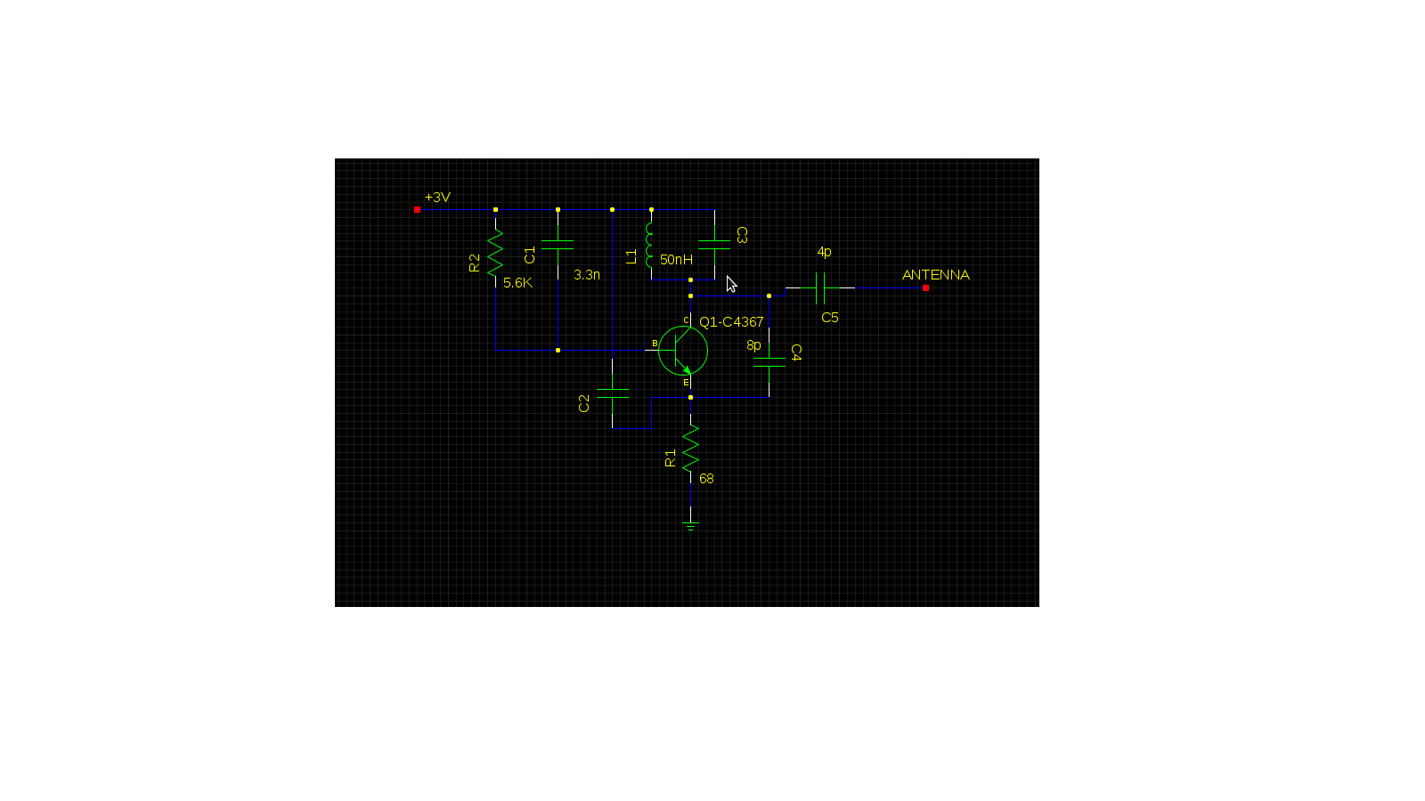
Im a newbie to RF design, and here is my problem.
Is it practical to design a 900Mhz collpits oscillator? well I have tried to reach that frequency but around f>300Mhz it starts to attenuate the amplitude.
Does anybody know what the reason might be or if there is any frequency limitation?because I have searched alot but I couldnt find anything.
I really appreciate your help.
 

Choose your L:C (or L:C:C) ratio so that it produces sufficient voltage swings, in view of the Amperes which are available to drive it.

It is common for the inductor value to be between a thousand and a million times the capacitor value.

A larger capacitor requires greater Amperes.

A smaller inductor requires greater Amperes.

Suppose your supply is under 10V. You might have a few mA travelling through your circuit. It should be possible to get a few V of swing at your LCC loop.

(Now I'm cheating by using a simulator.)

Therefore these are sample values which will yield 900 MHz:
2 pF and 40 nH.
3 pF and 23 nH.
4 pF and 16 nH.

This assumes resistor values in your circuit are under one kilohm.
 

    V

    Points: 2
    Helpful Answer Positive Rating
Thanks for the reply. Here is the schematic of my design. In this design For C3 I use a 10p trim capacitor. I guess that the LC values are OK. but I don't know which resistor you mean? Would you please take a look at my design to see if I'm doing anything wrong?I got the idea of this schematic from a FM transmitter.

 
Last edited:

2SC4367 has a typical transit frequency of 1 GHz (min. 600 MHz), so you're lucky if the circuit is oscillating at 900 MHz at all. You all want to use transistor with GHz bandwidth instead.

Apart from this point, what's the value of C2? Is your circuit layout suited for 900 MHz at all?

If you connected an antenna, it's frequency dependent radiation impedance may be sufficient to reduce the oscillator level with rising frequency or even stop oscillations. Similarly your measurement device (was is it) may have the same effect.

B.t.w.: Are you reporting real measurements or a simulation?
 

I'm reporting real measurements. I don't have any problem with simulation since I have another oscillator design the works properly with simulation but in practice it doesn't even start to oscillate.
If you are saying that the bandwidth gain is not suitable for my work (and I guess you are right because the datasheet says that too) then how come it is working over FM range (I was able to transmit a song using a microphone an receive it on a radio device).
The Value of C2 is 68p. I used a perforated board and assembled the parts on it.
I don't use an antenna and I use a 200MHz oscilloscope. I know that the frequencies doesn't match. But I think it should at least show the signal amplitude right.
 

Many problems:

- the 1 GHz transistor will work well for oscillators up to several 100 MHz, it may even oscillate at 900 MHz, but probably not in your setup
- a 200 MHz oscilloscope can't show correct signal amplitudes far above 200 MHz. It may indicate the existence of a signal at e.g. 500 MHz but hardly at 900 MHz.
- I presume you are using a passive oscilloscope probe. It represents a large capacitive and lossy load to the oscillator which can well stop UHF oscillations, even of a better oscillator.
- it's very difficult to make a 900 MHz circuit on a Veroboard without a massive ground plane.
 
I see what you are saying. I will make a PCB for test. And I will search for a GHz bandwidth oscillator. Do you have any idea how to test my circuit without the help of GHz oscilloscopes? Because I don't have access to one.
 

Status
Not open for further replies.

Part and Inventory Search

Welcome to EDABoard.com

Sponsor

Back
Top