Continue to Site

Welcome to EDAboard.com

Welcome to our site! EDAboard.com is an international Electronics Discussion Forum focused on EDA software, circuits, schematics, books, theory, papers, asic, pld, 8051, DSP, Network, RF, Analog Design, PCB, Service Manuals... and a whole lot more! To participate you need to register. Registration is free. Click here to register now.

LED batteries and set up

Status
Not open for further replies.
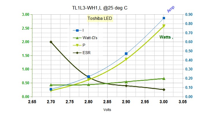
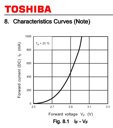
White or Blue high bright (HB) LEDs have a threshold is near 2.5 but ESR linear asymptote is around 2.85 and actual Vf forward voltage depends on W capacity * ESR of LED

.

There was another forum where you trying to explain the ESR concept. Sadly I lost the thread. I still have absolutely no clue as to a LED's "ESR" relevance or use in practical electronics.

The second part of your statement [that I bolded] is....................unusual. Care to elaborate?
 

If you search my threads you will find many graphs which show that all semiconductors saturate and have a more linear bulk resistance. Bigger means lower losses and high current ratings.

For FETs it is called RdsOn, for Vce_Sat in BJT's, companies with ultra low Vce_sat use a parameter called Rce which is the saturated switch resistance from which you can determine your heat losses.

For LED's they do not specify ESR but you can determine it from the tangent slope of the saturated VI curve. The same is true for any diode. From this you can estimate the forward voltage rise.

LED ESR.jpg Here an LED Matrix can be the same power but have more in series or in parallel with a number of chips in an array.
The upper LEDs with 2S2P are 6V are ~5.33@0A asymptote or 2.665 per LED
The lower LEDs are 4S1P are 12 V are 10.6@0A or 2.60 V per LED.
Then with 0.22 Ohm for each LED you can predict the rated current voltage and its linear variation.
For 5mm LEDs it is closer to 2.85V asymptote for ESR.

The CREE matrix LEDs here are rated as 28.8W max shared by 8 chips or 3.6W/chip
THe watt-ohm [WΩ] product for these are 3.6W*0.22Ω = 0.79 which is very good ( since it is less than the typ product term ~1, but is actually due to the NTC coefficient since these LED's are rated at 85'C and not 25'C std.
Maximum drive current: 4800 mA (6 V), 2400 mA (12 V)

Size of conductors also benefits with improved thermal response.

Note that all diodes and Semi's are rated at standard temperatures. Typically 25'C with with a pulse , but more recently at 85'C with constant current. There is always a NTC voltage effect on Diodes but a PTC effect in certain MOSFETS for easy parallel operation with no fear of mismatch and thermal runaway.
.
All batteries have an ESR which is inverse to size or capacity and the voltage drop after initial burden is quite linear and ESR rises rapidly towards end of SoC. This varies extensively with chemistry.

In thermal runway with BJTs and LEDs alike for parallel operation the ESR must result is a lower variation of voltage than the NTC effect of thermal resistance with losses from ESR to prevent thermal runaway.. If they are not well matched then a series resistance is selected equal to the maximum variation of ESR among the parallel array. Batches of LED's from an epiwafer are often all matched within 1 mV (@20mA) , so arrays of chips do not need equalization resistors. (scale this to 10mV @ 200mA within a batch. )

THe tolerance of Vf of Diodes in inverse with quality ( and cost), just like hFE can have a wide tolerance but a batch will be very consistent and are often binned to tighter tolerances in both to meet design requirements.

In my last order of 100k pc. of 5mm white LEDS from 2 suppliers and 2 shades of white each, the tolerance for voltage was tested for all and supplied as 3.0~3.2. Old technology parts were around 3.8 for 20mA but would be considered poor quality for a 2.2mm chip, but normal for a 1mm chip.. The ESR is typically around 15 Ohms, so the drop due to ESR @20mA can be estimated as 300mV above 2.8 or Vf=3.1.

ESR is not a precise figure but it increases with age in batteries, capacitors and LED's with smaller sizes. and is a very useful metric when you compare quality.
 

Appreciating the response. And please forgive for not responding [for obvious reasons] ... i think i will have to take a back seat on this one :thinker:

Just to confirm my intentions, i will be using a 'single' light for my products [either a blue one, or a white]

Has i said, i will eagerly await the outcome of this subject [many thanks] ... And thx to 'Zasto' for his observations.

Many thanks again, Vince

- - - Updated - - -

... Just to reiterate my requirements ... I am hoping to run a single LED light [white or blue], for approximately 360hrs [min.] before changing the batteries ... [i do realise that 360hrs is contrary to what i posted earlier ... sorry]

My only other requirement is to avoid any external wiring, or plugs.

Kind regards, Vince
 

Has i said, i will eagerly await the outcome of this subject [many thanks] ... And thx to 'Zasto' for his observations.
... I am hoping to run a single LED light [white or blue], for approximately 360hrs [minimum] before changing the batteries ...

My only other requirement is to avoid any external wiring, or plugs.

Kind regards, Vince

Which comes first? The cart or the horse?

We do not know which LED you will use [Vf is critical].

We do not know at what current you will operate the LED at.

If you determined the LED and current first, then choosing the battery is easier.


That said, start with a 3.7 Li-Ion Rechargeable Battery of at least 3600mAH [to run your LED at 5mA].
 
I would hate to buy batteries for such a thing

How about using a wireless charging for the battery?
**broken link removed**
 
Conceptually the radiation of wireless power is contradictory to the message in the object.

A base is the best compromise powered by friendly USB plug. Even a wireless phone is a contradiction.

No messy drilling or battery contacts or batteries.
 
If you search my threads you will find many graphs which show that all semiconductors saturate and have a more linear bulk resistance. Bigger means lower losses and high current ratings.

For LED's they do not specify ESR but you can determine it from the tangent slope of the saturated VI curve. The same is true for any diode. From this you can estimate the forward voltage rise.

Thank you for your prompt reply.

I did read several of your posts but it seemed to me that you [too] quickly jumped from one statement to another one.

I would like to find out;

1) How to calculate the ESR
2) Under what conditions it is valid, and its limitations
3) How to use it.
4) What advantages it has


The first item, then.......1) How to calculate the ESR

Under the condition that Vs > Vf [supply voltage > forward voltage]

{I suppose when you say saturated you mean that the supply voltage >= the forward voltage}

One either needs to measure the current at two 'reasonable' points or derive from the flatter portion of VI curve for the LED.

Although given that the relationship is largely linear, measuring at one point should suffice. Correct?

I do not know what you mean by the tangent slope - I know what a tangent is, but a tangent is the same as the slope for a linear relationship. [if y = mx +c, then y' = m so the tangent to the 'curve' is the same as the slope]

So are you saying it is non-linear?

"From this you can estimate the forward voltage rise." The Vf rises?
 
What do you understand on VI curves on batteries, diodes , transistors and MOSFETs and the thermal effects?

anything?

ESR is is just the incremental resistance in series with a junction fixed voltage drop. Thus from the VI curve slope or tangent = dv/di, which you can extract from a plot or a table of numbers.
When the resistance changes many decades at low current and stays within 50% over 1 decade or so, we call it saturated so that the semiconductive effect no longer changes and just the bulk series reistance affects the voltage rise with current.


In MOSFET's is useful over most of the Vds range and is called RdsOn. RdsOn is set by Vgs threshold and reduces with rising Vgs for predictable improvement. Below the threshold it is not predictable with Ohm's Law except during transients.

The same is true for CMOS logic by using the Vol/I_typ ratio or (Vcc-Voh)/I_typ. CMOS has gone from 300 Ohms to 25 Ohms now for ESR of the driver for advanced low power high speed logic like that used in MEGA CPU's.

In transistors it is when Vce is normally 0.2V for low current and 2V for very high currents. The variation of Vce_say is predictable from the specs for Vce_sat @ I. This is often call Rce or Rsat by Diodes Inc or as I call just call it, ESR.
example **broken link removed** R SAT = 60mΩ You can use Ohm's Law on the result.

In rechargeable Batteries after a light load, the idle charge surplus will be drained ( like a saturated semi ) and after this voltage drop will be linear with current rise. This is ESR = dv/di and you can use OHm's Law on the curve.
e.g. a car battery charged to 14.2 will drop to 12.5 with a light load and stay there until heavily loaded >1A and then if it drops 10mV per Amp then it is 10 milliOhms ESR.

Depending on the doping in transistors for B-C vs B-E there can be a fixed offset of 200mV or close to 0 in modern switches. Above this is is a linear R. This takes more effort than this to explain.

In Zeners, silicon diodes , Schottky , SiC diodes, GaAs and LEDs, there is the same characteristic of ESR above that junction threshold voltage .

I usually use 10% of rated to 200% current but depends on the tolerance range of the voltage available. It basically allows you to use Ohm's law for impedance ratios required on % tolerance voltage regulation or current regulation.

It would take me more time to make a text book answer and I could write a book on all the applications.
 
Instead of calculating the ESR of an LED then using Ohm's Law to calculate its forward voltage at different currents by looking at the graph that shows its "typical" forward voltage at different currents, why not simply look at the graph that shows you it without calculating anything??

The problem with graphs in datasheets is that they show only "typical" devices. The written spec's tell you that the minimum and maximum numbers are very different from the "typical" numbers shown on the graph. You can buy some very expensive LEDs that have their forward voltages tested and "binned" like the Cree LEDs used by SunnySkyGuy or you can buy cheap ordinary LEDs from a pile without knowing if they have minimum, typical or maximum forward voltages.
 
If you understand the concept of a linear ESR value in order to use Ohm's Law, you can solve problems jn seconds..

If you don't always have a table or graph of VI values, so you can use my Rule of Thumb ( Stewart's theorom ) to predict real world results like I did with the Lithium Photo cell and White LED.

If you don't want to use my experience , that's ok with me.

If you want to follow my Watt-Ohms~1 experience then degrade it x2 to x3 for poor quality products.
THe same derating applies to Battery quality ESR.

You can use it to understand the quality of products and I can explain other factors like the impact on temperature rise and Arhenius Effect and aging of LEDs... choose the cheapest method, qualify new brands for buyers based on ESR tolerance or compare new products , measure aging in batteries, use ESR for Caps to determine ripple voltage is analogous to supply variation to LED brightness variation given the ratio of ESR to total series resistance * supply tolerance..

You can estimate the ESR of a 2kW 1500A diode (hockeypuck) the same as 50 mw SMD LED and how it will behave to regulating the current...
It's not just Cree LEDs, it applies to ALL DIODES.

or comparing a large Lithium pack to a small coin cell and readily understand why a coin cell with 2kohm ESR (effectively or efficiently) cannot possibly run an LED with 16 Ohm ESR.

It's a very useful concept... if you understand tolerances and Ohm's Law.

The optimal unregulated design is one with tight voltage tolerances on supply voltage and is just above the threshold voltage of the diode for low loss. This applies to zeners as well
In effect you want to match the loaded supply voltage to the loaded diode voltage and then you can factor the variation of current with variation of ESR tolerance. ESR tolerance can be cut in half by adding a small series R to each parallel string of unknown LEDs.
e.g if each LED is 20 Ohms. +/-50% (poor) the variation is 10 Ohms so adding a series R of 10 Ohmss 1% reduces the overall tolerance now +/-25% If supply V variation is 2% then current variation is now 1.02/-.75= 1 +36% worst case.
if you know your diodes are matched in the same batch then ESR variation is closer to <3% so with R=0 then current variation initially is 1/02/0.97= 1 + 5% when you choose a fixed voltage.

I used this same principle for putting unknown CREE LEDs with 4 in a string and 5 strings in parallel without any R on a random SMPS 25W 12V wallwart with excellent results as expected an no thermal runaway.
12V on 4x3.0 with a threshold of 2.85V, I knew these LEDs were rated for 3W with heatsink so each LED had an ESR of 1/3 Ohm and 4 LEDs had the result of approx 4x2.85V +4x 1/3R or 11.4V+ 1.33R characteristic.
I expected the SMPS to be 2% so 2% of 12V is 0.24V/1.5A = 0.16 Ohm ESR for the source. Now applying Ohm's Law with total resistance 12-11.4V=0.6V & ESR_tot= 1.33+0.16= 1.5 Ohm , I= 0.6V/ 1.5R= 400mA which is about what I measured. within 25%. and well under the max current. and well under the max brightness which I did not want for this application.
IMG_1475a.jpg

But in another case I want maximum brightness with a Logitech SMPS Wallwart rated at 20V, 1.5A so I chose 2 strings of 6 LEDs. I used the same reasoning for 2% on supply or 40mV/1.5V = 27 mOhm ESR
THis time I used two strings of 6 LEDs or 2P6S array. Result LED load = 6* (2.85V + 1/3 Ohm) = 17.1V + 2R, thus with a 20V supply I got 2.9V/2R =1.45A using 96.7% of the rated power of 30W and 100% of that power delivered to the LED array with NO SERIES R required. If I had a 21V supply I would need to add 1V/1.5A =0.67R 2W Resistor, so I was lucky. If a series R is needed it should ALWAYS be less power than the rated LED, otherwise add another LED to the string and use a smaller Rs.

photo.JPG This is the result of 20W's of surplus LED and surplus SMPS in a sliding closet with 100% efficiency in regulating the LEDs R=0


So in short

White LED equation = 2.85V +I*/watt rating for each device running in series or parallel. Then use Ohms law I = excess voltage/ total ESR ( drop inside LED, wire and supply)

Keep in mind if running near max power, it must have a thermal design to match the low ESR device.
 
Which comes first? The cart or the horse?

We do not know which LED you will use [Vf is critical].

We do not know at what current you will operate the LED at.

If you determined the LED and current first, then choosing the battery is easier.


That said, start with a 3.7 Li-Ion Rechargeable Battery of at least 3600mAH [to run your LED at 5mA].

Has i have said before, i would like to know what i would need to run a single LED light [blue or white], for approximately 360hrs [+]. Has i do not know anything about LED bulbs etc, i obviously remain open to any bulb.

This has turned out more complex that i imagined. In my ignorance i thought that there may be a relatively simple answer ... In all honesty [to my embarrassment] i was hoping for a reply that listed the bulb, battery and resister [if required] :-|

Again, many thx for the replies ... even though i'm lost .. haha

Kind regards, Vince
 

Don't stay lost. Simply follow a couple of rules:
1) Buy an ordinary cheap 5mm diameter white LED, a 330 ohm 1/4W resistor and a new name-brand 9V alkaline battery.
2) Drill a hole in one of your pyramids and try it!
3) Also try an ordinary cheap 5mm blue LED with the same resistor and battery.

If it is not bright enough then try an ordinary 10mm diameter LED with a 150 ohms resistor.
If it is still not bright enough then you need one of those "special" LEDs that are very bright and can use a lot of current.

4) When the LED and current are known then battery spec's can be calculated.
 
If you can define the the maximum volume the battery can take and suggest a competition at any reasonable price, I think the Lithium 3.0V Photo cell or CR123A directly on One BLue or White LED or one Red or Yellow with a 1V drop resistor will work for the longest duration.

If you dont limit size, then other lossy inefficent methods with resistors and lower density batteries will work, but poorly.

Unfortunately your specs for size, cost, and brightness are lacking to solve

None will be bright for 360 hrs.
But you can add a ~10mA current limiting resistor to my solution and have it dim for 360hrs.

What you need:


All from Digikey can be ordered and shipped same day.


Proof:

Vth @10mA = 2.55V of Toshiba TL1L2 @ 10mA
Vbat 3.0V R = 0.45/0.010 = 45 Ohm choose nearest value in stock, like 40
Amp-Hour load = 10mAh
Battery capacity depends on quality and source.
But if 1300mAh is true at C/10 it may be 20% more at C/100

but assume 1300/10 =130 h

I dont think you will find a better solution.

Ensure soldering is quick and sealed with clear epoxy with LED so prevent breakage of solder joint.then insert and epoxy spring clips soldered with AWG30. to fit under pressure contact . then insert battery and screw base such as FR4 circuit board material to bottom. For aesthetics, apply dark colour epoxy to bottom of clear dry epoxied LED to hide battery or use Alum foil..

Note to run this LED at 1A is possible with large heatsink and will be the brightest little torch with a LiIon 3.7V battery and DC-DC CC regulator. ( blinding bright )

Walmart sells these $0.90 batteries for $5.78 .. so I would suggest change Batteries not included to Optional
Panasonic are better but cost more even on Ebay.

If you are clever, you can use another battery spring contact as a switch to bypass the 40R resistor and get upto ~350 mA but deplete battery faster. and dissipates 1W so gets very hot and can burn out. so add series leaky 10,000uF cap to make a 5ms flash pulse for camera pictures. https://www.digikey.com/product-detail/en/EMVA6R3GDA103MMN0S/565-2071-2-ND/756718 $3

Also you need an on/off switch using more battery contacts
If you want different colours, say so.

More work needed on mechanical design, but now you have a solution.
 
What do you understand on VI curves on batteries, diodes , transistors and MOSFETs and the thermal effects? anything?
I understand the VI curves, just fine. Although I suggest keeping the scope of the discussion restricted to LEDs at present.

- - - Updated - - -

ESR is is just the incremental resistance in series with a junction fixed voltage drop. Thus from the VI curve slope or tangent = dv/di, which you can extract from a plot or a table of numbers.


There is no tangent, unless the curve is non-linear.
A tangent line is a linear line that intersects a curve at only one point. It has the same slope as the curve at that point.


You can not use the average slope [as you did in the VI diagram] and then call it a tangent.

You need to use the correct term.


Assuming you really mean the [average] slope of the [linear portion] of the VI curve, we have 2 problems.

The first problem is that the calculating the slope is somewhat subjective since it is not entirely linear, and the choice
of the two points influences the resulting slope. If you asked 10 people to calculate the slope, you could get 10
different values.

The second problem is that the [average] slope is no longer resistance. It is the [average] rate of change of
resistance. V/I gives resistance. But dV/dI gives the resistance rate of change. It is a subtle but important point.

- - - Updated - - -

I usually use 10% of rated to 200% current but depends on the tolerance range of the voltage available. It basically allows you to use Ohm's law for impedance ratios required on % tolerance voltage regulation or current regulation.
.


Is this relating to the two points on the VI curve? So your first point in determining the slope is 10% of the rated current, and the second point is 200% !!!
Why 200%!
Is not very non-linear at that point?


Where did impedance came from - you lost me. I do not see the relationship. W were talking about resistance, and it has morphed into impedance?
 
Many thx to all of the replies, and a very special thx to 'SunnySkyguy' and 'Audioguru' for sticking with me ... [the patience of angels]

I will look into the advice, and 'chew this over' the weekend. Thank you.

Much appreciated, Vince.
 

Kam, I can prove everything I have said is true.

Later I need to explain to you how I derive the fixed point tangent for measuring ESR to get a 1st order equation with a fixed Vth and ESR to match a power series equation and both give the same true LED VI curve.


I'll let you digest this.

6384347900_1429964836.jpg


  • What I have done is reducing a power series to a 1st order equation to get < 2% error.
  • There are datasheet curves extracted into a spreadsheet and then calculations applied for P, ESR and ESR*P.
  • I am refer to ESR in two ways.

    1) A dynamic Rs ( power series) as the tangent or apparent Effective Series Resistance ( for a small variation) shown in plot
    2) A fixed ESR from a fixed asymptote to If=0 where V=Vth ( threshold)
  • Not shown here and it is not obvious is that the best Fixed ESR value for predicting the Vf vs If requires a constant I choose based on the rated power, temperatures
  • I have claimed in past as Stewart's Theorem ( with tongue firmly planted in cheek)
  • There is one point, where a Vth & a fixed ESR can be selected to predict typical Vf vs If.
  • It is based junction temperature, power handling, cooling and junction size which is below the Absolute Maximum Rating and the Watt-Ohm product.
  • Another point is; Production tolerances are asymmetrical and skewed positive for ESR and resulting Vf at rated If and sorted bin ranges may be elected to reduce prediction errors.
  • Vled = V1 + I * dv/dI * k where dv/dI is the power series V/I tangent slope or apparent quadradic ESR ........... (1)
  • Vled = Vth +I*ESR ( where ESR is a constant number) ................. (2)
  • In this case this LED at 25'C my result is below;
  • ( discussion on correction to actual Tj, and Vf correction (later) depends on deg C/W and mV/deg C)

    at 25 °C

    for (1) Vled = V1 + I * dv/dI * k

    from iterations

    V1 = 2.100 V , k=4.1V, dv/dI is from graph ( ESR ) not to be confused with fixed ESR I use with (2)


  • resulted in error < 2.1% in Vled

    for (2) Vled = Vth +I*ESR

  • n.b. I chose 2.90V where junction is saturated and fairly linear above this , which is almost 50% of the Absolute Max current and power of the device.

    Vth = 2.710 V , ESR = 0.400 ............ (3)


  • resulted iin error <1.8% in Vled

my error in digitizing Toshiba graphs ~1%
4362456700_1429970752.jpg


calculated Vled from (2) using (3) and I only.

VIESRPWatt-Ω'sVledError
2.700.082.000.2160.432.7421.6%
2.800.220.710.6160.442.798-0.1%
2.900.470.401.36590.542.8984-0.1%
3.000.860.262.5830.663.05441.8%


At the risk of being too verbose or too brief, do you follow my points yet? :cool:

I realize this is way beyond the scope for Vincent, but I had to support my arguments and I wanted Kam to understand this so matching the power source ESR and voltage to the load is key to a simple unregulated solution of running a LED or string from a fixed voltage or a good battery.

Power density, size and runtime for LEDs and size of battery, Vincent will calibrate his thinking with experience, I believe.


**broken link removed** Originally Posted by SunnySkyguy **broken link removed**
I usually use 10% of rated to 200% current but depends on the tolerance range of the voltage available. It basically allows you to use Ohm's law for impedance ratios required on % tolerance voltage regulation or current regulation.
.


@Kam
Is this relating to the two points on the VI curve? So your first point in determining the slope is 10% of the rated current, and the second point is 200% !!!
Why 200%!
Is not very non-linear at that point?

Note. Vth = 2.71 is near 100mA or 10% of Imax=1 A
I=500mA near where ESR was chosen for practical thermal operating point can be pulsed 200% to 1A for a flash using my equation accurately with a fixed ESR.
 

Status
Not open for further replies.

Similar threads

Part and Inventory Search

Welcome to EDABoard.com

Sponsor

Back
Top