Welcome to our site! EDAboard.com is an international Electronics Discussion Forum focused on EDA software, circuits, schematics, books, theory, papers, asic, pld, 8051, DSP, Network, RF, Analog Design, PCB, Service Manuals... and a whole lot more! To participate you need to register. Registration is free. Click here to register now.
I want to build a circuit which will give square wave current waveform with 2 levels, 7mA and 14 mA and duty is fixed 50% and frequency is varying.
Please suggest solution.
- Frequency Range is 1 Khz to 30 Khz
- Unipolar output.
- Current source compliance spec, i don't have it.
it is basically sensor output.
I want to create a circuit which will give output like sensor will give.
Sensor output is square current waveform. with 2 levels 7mA and 14mA.
_____ _____ <-- 14mA
| | | |
| | | |
| | | |
__| |___| |_____ <-- 7mA
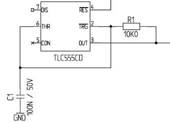
I guess you can use a timer IC (555 timer) to produce a square wave with varying frequency. Then feed it to voltage divider network to get the required output voltage corresponding to the 7mA / 14mA current levels. This has to be given to the 4-20 mA current Tx IC like XTR117. In this way you will be making use of standard current Tx output which may be similar to the sensor.
The IC XTR117 has got sufficient bandwidth to work till 30kHz input.
If the mark/space ratio is critical, I would use the 555 just as an oscillator running at twice the desired frequency then follow it by a bistable. The current range is trivial, but you have not said what your load impedance is, if its 100K, then you need a circuit with an output impedance of 1M ohm at minimum, like wise if you have not said what the maximum voltage could be. If the load is really 100K and the current really is 14mA then you need 1400 V as a minimum for your supply voltage.
Frank
This site uses cookies to help personalise content, tailor your experience and to keep you logged in if you register.
By continuing to use this site, you are consenting to our use of cookies.