Continue to Site

Welcome to EDAboard.com

Welcome to our site! EDAboard.com is an international Electronics Discussion Forum focused on EDA software, circuits, schematics, books, theory, papers, asic, pld, 8051, DSP, Network, RF, Analog Design, PCB, Service Manuals... and a whole lot more! To participate you need to register. Registration is free. Click here to register now.

padding of zeros llogic in verilog

Status
Not open for further replies.

anusha vasanta

Member level 1
Joined
Sep 23, 2014
Messages
34
Helped
0
Reputation
0
Reaction score
0
Trophy points
6
Activity points
251
hello help me with this issue. i am having 65 bytes of my original data i need to get some 80 bytes of data_new .(65+15) in this i need to pad 15 bytes of zeros i implemented this using counter but still getting some issue with using temp reg here.help me with this .thankyou
 

code

Code Verilog - [expand]
1
2
3
4
5
6
7
8
9
10
11
12
13
14
always@(posedge clk or negedge reset)
   begin
    if(!reset)
       data_new<=0;
     else
     begin 
       for(count=0;count<15;count=count+1) 
     begin 
      [7:0]temp[64:0]<=[7:0]data[64:0];
      [7:0]data_new[79:0]<={[7:0]temp[64:0],8'b0}; 
      [7:0]temp[64:0]=[7:0]data_new[79:0];   
     end  
     end
    end


Show your code.

- - - Updated - - -

The first assignment to temp will be ignored according to non-blocking behaviour.


Code Verilog - [expand]
1
2
3
4
5
6
7
...
       for(count=0;count<15;count=count+1) 
     begin 
      [7:0]temp[64:0]<=[7:0]data[64:0];
      [7:0]data_new[79:0]<={[7:0]temp[64:0],8'b0}; 
      [7:0]temp[64:0]=[7:0]data_new[79:0];   
     end


What is it you expect this block of code to do? Also how do you expect this to synthesize? The use of [7:0]temp... is illegal syntax. You can't have a range in front of the signal name.

Also why is there a for loop in the code, you don't even use count to index anything. It doesn't belong in this code. You shouldn't repeat identical assignments, that is like adding a 16 jumper wires on a board between the same two pins on a board.

Your original question was about 0 extending a 65-bit value into an 80-bit value, that is simple in Verilog.

Code Verilog - [expand]
1
2
3
4
5
// if you don't want warnings about assigning a 65-bit to a 80-bit
data_new = { {80-65{1'b0}}, data};
 
// if you don't care about warnings, Verilog automatically 0 extends a smaller width to a larger width (it also truncates)
data_new = data;


- - - Updated - - -

Oops, I see you are appending the 0's.

Here you append like this:

Code Verilog - [expand]
1
2
3
4
5
6
7
data_new <= { data, {80-65{1'b0}} };
// or simply:
data_new <= { data, 15'b0 };
 
// or another trick, but others will probably wonder about your coding ability.
data_new <= 0;
data_new[79 -:65] <=  data;


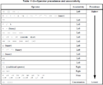
That last one is deliciously hideous. XD As for the first one, are you sure that the operator precedence for - (minus) is higher than for the { } replication operator?
 

That last one is deliciously hideous. XD As for the first one, are you sure that the operator precedence for - (minus) is higher than for the { } replication operator?

Absolutely sure of it...
Capture.PNG

It's at the very bottom :)

And that last example, I've actually used similar stuff on occasion when I was loading bit slices into another register with offset fields, which were getting indexed using a for loop. Needless to say, I added a large amount of comments describing the bit-slicing.
 
Last edited:

Just checked it. You are right, the minus takes precedent.

Edit: Ah, you already provided the list. Yeah, I couldn't find a reference list fast enough. But I had a simulator window open so use that as double check. Anyways, LRM section 11.3 noted.
 

I probably abuse Verilog to the utmost, if it can synthesize and makes my code easier to parameterize I'll do it ;-)

I've even attempted stuff like this before:
Code:
signala[addra[4*idx +:4]] <= signalb[addrb[8*idx+2 +:4]];

though synthesis tools typically choke on stuff like this, usually with no error just a broken design that doesn't synthesize properly. :bang:

Oh, yeah this should end up as simple muxs that are addressing an array on both sides of the assignment.
 

As for the -: style bit-slicing, I don't mind using that in a for generate block. Just this particular one is a bit hideous. :p So let's go with the middle one. :)

- - - Updated - - -

I've even attempted stuff like this before:
Code:
signala[addra[4*idx +:4]] <= signalb[addrb[8*idx+2 +:4]];

Heh. I tend to put () brackets around things like (8*idx+2) and then an extra space before the 4 so the intent is clear. If it doesn't synthesize then, well sod the synthesizer. :p

Plus brackets sometimes help the parser be greedy at the right places... Just in case the one writing the parser was in a hurry for that particular bit of the implementation.
 

As for the -: style bit-slicing, I don't mind using that in a for generate block. Just this particular one is a bit hideous. :p So let's go with the middle one. :)
The :evil: side of me had to include it, without the for loop.
 

As for the really creative constructs ... I have learned to NOT do that and stick with the totally boring. Because while I happen to think a construct is totally legit, the sucky tools sometimes don't agree. Sometimes I SO hate that. You have a perfectly elegant way of expressing something, and tool XYZ does not accept it as valid. But regarding HDL tools I have learned to set the bar looooooow.
 

//code//


Code dot - [expand]
1
2
3
4
5
6
7
8
9
genvar count;
    generate 
    // to append the zeros to the existing data to make it divisible by 16
    for(count=15;count<0;count=count-1) 
    begin 
     assign data_new= {data_in,8'b0}; 
     assign data_in=data_new;    
    end   
    endgenerate


//is this a proper one for each count i need to pad 8bits of zeros so that data finally my data of 65 bytes will be preceeded with another 15bytes of zeros making it a 80bytes of data.Help me with this thanku all....
 
Last edited by a moderator:

[Moved]implementation problem in asic and fpga??

Hi all,
is it advisable to use generate block in dut for our logic purpose even we can do it in always block.is gen block create any issues of memory during implementation and what we get as macro when we write generate block.answer me as soon as possible
 

Unfortunately you don't show the variable definitions belonging to the code snippet. Apparently you didn't yet think about the actual size of the vectors. Otherswise you had noticed that LHS and RHS of the assignments have different length and cause syntax errors. Assigning a new value to data_in will also cause a multiple driver issue in continuous code.

It's not clear why you are using generate. Isn't it just

Code:
assign data_new = {data_in, 15{1'b0}};
 

in the above code data_in is of 65 bytes size and data_new is of 80 bytes. instead of assigning data_new={data_in,8'b0} can i store data_in in a temp reg of 80 bytes so that each time for my 65 bytes of data for 15 counts there will be 15 bytes of zeros will be padded.
 

I'm pretty sure at this point you are a software programmer that thinks they can write Verilog Software. Wrong, Verilog is a hardware description language. Your idea of counting (from the software world) is to use a for loop. Won't work for a hardware design i.e. Verilog RTL. If you want to count you need to use a clock and a physical register pluse an adder to increment the output of the counter register and stick the incremented value back into the register. Verilog for loops are used to make multiple copies of what ever is in the for loop. Those copies normally use the index to perform bit-slicing and select an item from an array of some sort.

If you wish to take 15 clock cycles you can left shift the 65-bit data by 15 bits to pad the data. Seems pointless as the shift is really just how the two registers are wired up.

- - - Updated - - -

Whoa, I totally missed that you are zero padding 15 bytes of data to a 65 byte data packet. You should have said something about packets or blocks of data. I was reading your posts as 65 bits, which you never pointed out and corrected anyone on. I realize now my mistake was due to seeing your non-functional code. You should present what you are trying to do in C or pseudo code.

If you are trying to pad with 0's how is your byte data organized? Is your byte data packed wire [80*8-1:0] data_new? Or is it in an array wire [7:0] data_new [0:79]? Does your byte data show up as one bit 65-byte word or as 65 individual bytes arriving one after another (streaming)? Depending on the answer you will have to perform different operations to load the 65-bytes into the 80-byte packet.

If the data_new is a large register then I would use a demultiplexer to load each byte (or multiple bytes 65 of them) into the various fields of the 80-byte register. This could be as simple as:
Code:
// direct assignment
assign data_new[80*8-1:0] = {data[65*8-1:0], {15{8'b0}}};

// indexed assignment per byte with array deffinitions
for (i=0;i<80;i=i+1) begin
  // i assumes that the most significant bytes of the data_new array are at the lowest index.
  assign data_new[i][7:0] = i<16 ? 8'b0 : data[i][7:0];
  // If you are little endian then 80-i and 65-i would be used:
  // assign data_new[80-i][7:0] = i<65 ? 8'b0 : data[65-i][7:0];
end

All of the above assumes that data and data_new are held in registers so all the bytes can be accessed in parallel. If data and data_new are in a memory or are streaming bytes then you need to have a FSM to monitor the byte stream and load the data_new memory or perform the zero fill padding insertion.
 
Status
Not open for further replies.

Part and Inventory Search

Welcome to EDABoard.com

Sponsor

Back
Top