Continue to Site

Welcome to EDAboard.com

Welcome to our site! EDAboard.com is an international Electronics Discussion Forum focused on EDA software, circuits, schematics, books, theory, papers, asic, pld, 8051, DSP, Network, RF, Analog Design, PCB, Service Manuals... and a whole lot more! To participate you need to register. Registration is free. Click here to register now.

doubt in VHDL testbench

Status
Not open for further replies.

abu9022

Member level 3
Joined
Jan 2, 2013
Messages
60
Helped
1
Reputation
2
Reaction score
1
Trophy points
1,288
Activity points
1,715
Hi friends

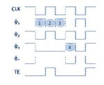
I have the Test Enable signal(TE) te.JPG which should be write in VHDL,
Code:
  clkperiod : integer := 4;           -- system clock period

Code:
 signal clk : std_logic := '0';
 signal te : std_logic := '0';
 constant ct : integer := clkperiod/2;

clk is already written
Can I know how to write TE signal, below one is correct?

Code:
  clk <= not clk after ct * 1 ns;
  te <= '0' after ct * 1 ns, '1' after ct * 1 ns, '0' after ct * 1 ns, '0' after ct * 1 ns;
 

I'm not sure what you are trying to accomplish, but the te assignment will result in nothing happening as you keep reassigning the signal at 2 ns. So the end result is that te stays low and never toggles.

Also according to your picture clock should start at 1 but your clock starts at 0.

given the clock you have this te will toggle the te on the first clock pulse only:

Code:
te <= '0' after ct * 0 ns, '1' after ct * 1 ns, '0' after ct * 2 ns, '0' after ct * 5 ns;

Note that each after clause has an offset of #ns that matches the number of clocks edges away the transition should occur. Though both the 0 ns and 5 ns ones are redundant as te is already 0 when they are both being assigned.
 
Last edited:

Status
Not open for further replies.

Part and Inventory Search

Welcome to EDABoard.com

Sponsor

Back
Top