Continue to Site

Welcome to EDAboard.com

Welcome to our site! EDAboard.com is an international Electronics Discussion Forum focused on EDA software, circuits, schematics, books, theory, papers, asic, pld, 8051, DSP, Network, RF, Analog Design, PCB, Service Manuals... and a whole lot more! To participate you need to register. Registration is free. Click here to register now.

Actel (AGL060V2) FPGA not getting programmed

Status
Not open for further replies.

behrazv

Newbie level 4
Joined
Jun 24, 2014
Messages
5
Helped
0
Reputation
0
Reaction score
0
Trophy points
1
Activity points
41
Hi everyone,

We have a custom board with the AGL060V2 FPGA (Actel) and the FPGA is not getting programmed. Programmer gives me an error:
Error: programmer '92256' : Signal Integrity Failure
Integrity Check Pattern Not Found.
Integrity Check Pattern :
550FAAF000FF0000FFFF
IrScan Error.
TDO stuck at 1
Chain Analysis Failed.
Error: programmer '92256' : Data Bit length : 8272
Error: programmer '92256' : Compare Data : FFFFFFFFFFFFFFFFFFFFFFFFFFFFFFFFFFFFFFFFFFFFFFFFFFFFFFFFFFFFFFFFFFFFFFFFFFFFFFFFFFFFFFFFFFFFF...
Error: programmer '92256' : Scan Chain FAILED.
Error: Failed to run Action.
(Sometimes TDO is stuck at 1 sometimes at 0 - with a long sequence of zeros after "Compare Data".

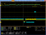
Here are the screenshots for TDI, TDO, and TCK:
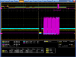
140625_153301.png

140625_153315.png

Do you know what the issue could be?

There is also a problem with the power - the VCC is pushed to 2.7 when 3.3V is connected to VJTAG. When we connect 1.5V to VCC, FPGA draws 50 mA and still the VCC remains at 2.7V. The screenshots are made for the case when VCC is floating, but if we do connect VCC to 1.5V nothing is working either - same error.

Please help.

Thank you in advance! :)
 

There is also a problem with the power - the VCC is pushed to 2.7 when 3.3V is connected to VJTAG. When we connect 1.5V to VCC, FPGA draws 50 mA and still the VCC remains at 2.7V. The screenshots are made for the case when VCC is floating, but if we do connect VCC to 1.5V nothing is working either - same error.

Based on your description, which I hope isn't correct you've fried the part. VCC isn't allowed to go above 1.65V per the data sheet:
Capture.PNG

I think you should post the schematic for the configuration logic you've got on the board, seems like something is connected incorrectly.

It's also not good for a lot of devices if you disconnect the VCC for the device and drive the IO voltages only. Don't know if this is the case for these Igloo's but it will take too much reading to verify.

- - - Updated - - -

BTW did anyone verify the power planes weren't shorted prior to applying power? Also did anyone check if the supplies were outputting the correct voltage for each rail before connecting the supplies to the rest of the circuits. (Good reason to have beads between the supply and the power planes).
 

Based on your description, which I hope isn't correct you've fried the part. VCC isn't allowed to go above 1.65V per the data sheet:
View attachment 106679

I think you should post the schematic for the configuration logic you've got on the board, seems like something is connected incorrectly.

It's also not good for a lot of devices if you disconnect the VCC for the device and drive the IO voltages only. Don't know if this is the case for these Igloo's but it will take too much reading to verify.

- - - Updated - - -

BTW did anyone verify the power planes weren't shorted prior to applying power? Also did anyone check if the supplies were outputting the correct voltage for each rail before connecting the supplies to the rest of the circuits. (Good reason to have beads between the supply and the power planes).

Thank you for your reply!

We did check the power planes and the voltage supply - everything looks correct. We also have another board with a somewhat different design that has the same voltage problem but is still getting programmed.

Also I took some more screenshots for TDI and TMS of the board that is getting programmed and the board that is not:
https://obrazki.elektroda.pl/4793096100_1403818305.png

It seems like everything just randomly stops working at some point in time and we cannot find a reason.

Thank you!
 

Your voltage levels in both cases don't look good. You should post the schematics of the configuration logic that you have for both the working and non-working board. I'd also check all the pullup/pulldown resistors around the configuration logic and make sure they match the values suggested by the manufacturer. Other than that I can't make any useful suggestions based on a few waveform captures on a scope.
 

Your voltage levels in both cases don't look good. You should post the schematics of the configuration logic that you have for both the working and non-working board. I'd also check all the pullup/pulldown resistors around the configuration logic and make sure they match the values suggested by the manufacturer. Other than that I can't make any useful suggestions based on a few waveform captures on a scope.

This is the schematics for the things connected to the FPGA. We removed the voltage regulators and are supplying the power from the power supply https://obrazki.elektroda.pl/1306510600_1403823398.png. The board does not program regardless whether we connect the 1.5 V (which raise to 2.7 V even when we don't limit the current).

What do you mean by configuration logic?
 

What do you mean by configuration logic?
My mistake I meant to say programming logic, which in this case is the power rails and anything connected to the JTAG scan chain.

What is connected to the molex3 TCK, TDI, TDO, TMS, and TRST? Do you have some special connector to a FlashPro programmer? Or do you have some custom way to program the device?

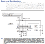
You also didn't follow the recommended connections shown in this diagram in the Microsemi documentation:
Capture.PNG
I notice you don't have the VPUMP isolated from the VJTAG and the VPUMP isn't connect to ground through a 0.33uF and 0.01uF. It's recommended that the VJTAG and VPUMP not share a supply rail.


Regards
 

My mistake I meant to say programming logic, which in this case is the power rails and anything connected to the JTAG scan chain.

What is connected to the molex3 TCK, TDI, TDO, TMS, and TRST? Do you have some special connector to a FlashPro programmer? Or do you have some custom way to program the device?

You also didn't follow the recommended connections shown in this diagram in the Microsemi documentation:
View attachment 106741
I notice you don't have the VPUMP isolated from the VJTAG and the VPUMP isn't connect to ground through a 0.33uF and 0.01uF. It's recommended that the VJTAG and VPUMP not share a supply rail.

Regards

Thank you for your suggestions. We tried adding capacitors (we didn't have 0.33 uF though - but our values were close). It's still not programming TOT.

As for the connector - we have a FlashPro4 (Microsemi-made) connector soldered to the Molex ribbon cable that inserts into the Molex connector on the board. We checked the resistances of the signal paths - they don't seem to be more than an Ohm each.
 

Status
Not open for further replies.

Similar threads

Part and Inventory Search

Welcome to EDABoard.com

Sponsor

Back
Top