Continue to Site

Welcome to EDAboard.com

Welcome to our site! EDAboard.com is an international Electronics Discussion Forum focused on EDA software, circuits, schematics, books, theory, papers, asic, pld, 8051, DSP, Network, RF, Analog Design, PCB, Service Manuals... and a whole lot more! To participate you need to register. Registration is free. Click here to register now.

[SOLVED] BWD 525 - horizontal trace clips to the right

Status
Not open for further replies.

jdimeglio

Junior Member level 1
Joined
Mar 19, 2014
Messages
19
Helped
0
Reputation
0
Reaction score
0
Trophy points
1,281
Location
Australia
Activity points
1,532
photo.JPGView attachment BWD 525 manual.pdf

Hi,

i can't figure this one out - any input will be appreciated - last time the response was great and ended up repairing my focus issue.


The Problem

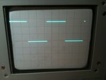
My max horizontal defection doesnt 'deflect' across the screen. The trace cuts short on the right by -2.5mm from the right edge of the grid - the wall.(with the timebase plugged in)

see image.

I have checked the horizontal deflection amp and i'm getting the +95/+98 as graphs suggest in the service manual.
Also all the supply voltages are all perfect. Applying an ext input also clips the horizontal trace - ie: no change.

The coarse & fine horizontal adjust "works" - when scrolling left it scrolls off the screen as expected but when scrolling to the right it clips. Hitting the same wall.


Its as if the entire trace shifted to the right as someone pointed out. I've measured the powersupplies all good - in fact perfect. About the only thing ive found strange was the voltage at the input (c) on the voltage was twice what it should be -3.5v to -4.15v instead of -2v to -2.8v. However the voltage swing on the horizontal amp outputs (e) & (d) are perfect.

Also when i plug in the 6T Time Base module into the CRO - according to its spec's it will allow the horizontal trace deflect by another 20% and yep it does.

Any ideas?

thanks
 

It's possible a piece got dislodged and is blocking the electron beam.

Have you tilted the unit at various angles? Do you see or hear anything move around inside the CRT?

Try unfocussing the dot so it is a disk. Turn knobs to move it to the problem area and examine for detail. Does the disc end sharply (as though physically blocked), or softly (as though the horizontal voltage is insufficient amplitude)?

Have you tried turning the sweep length adjustment inside the unit? This is different from the horizontal position adjustment on the front panel.
 
Thanks for the response.

@BradtheRad - i'll check but generally i haven't heard anything rattle and i've had the CRO on it side, upside down, etc while measuring voltages. If i'd have to guess i say i'd lean towards the disc ending sharply.

While the disk is in the "middle" of the screen it has a nice flat/sharp right edge - as it draws closer to the right wall the edges become rounded but most of it remains sharp at that point of intersection - the wall.

re: adjusting the sweep length - i can't see where to do that. I also found that the 7400TTL output voltage is twice as high (~4v rather than the 2.2v). I only have 74LS00 (which i now suspect is faulty) but it returned the voltage spec down to 2.2v but no sweep. So i've ordered another 74LS00 to see if that helps. ie: pg 63.

Can things get dislodged in CRT? - What such as a coil or something?


@SunnySkyguy - yep that the horizontal position adjust. That's what ive been using.
 

You just have to adjust the capacitor on the probe itself, usually you will find a trimmer on the probe which can be adjusted using a plastic screw-driver and an adjustment test point on the oscilloscope itself from where the signal is taken, so connect the probe to that point and adjust.

View attachment 103821View attachment 103822

Hi,

i can't figure this one out - any input will be appreciated - last time the response was great and ended up repairing my focus issue.


The Problem

My max horizontal defection doesnt 'deflect' across the screen. The trace cuts short on the right by -2.5mm from the right edge of the grid - the wall.(with the timebase plugged in)

see image.

I have checked the horizontal deflection amp and i'm getting the +95/+98 as graphs suggest in the service manual.
Also all the supply voltages are all perfect. Applying an ext input also clips the horizontal trace - ie: no change.

The coarse & fine horizontal adjust "works" - when scrolling left it scrolls off the screen as expected but when scrolling to the right it clips. Hitting the same wall.


Its as if the entire trace shifted to the right as someone pointed out. I've measured the powersupplies all good - in fact perfect. About the only thing ive found strange was the voltage at the input (c) on the voltage was twice what it should be -3.5v to -4.15v instead of -2v to -2.8v. However the voltage swing on the horizontal amp outputs (e) & (d) are perfect.

Also when i plug in the 6T Time Base module into the CRO - according to its spec's it will allow the horizontal trace deflect by another 20% and yep it does.

Any ideas?

thanks
 

If the defucussed spot can't reach the right side it suggests something is casting a shadow and it has to be between the tube cathode and the screen. That means something external to the tube is bending the beam (unlikely) or one of the deflection plates has come adrift. Both these failures would tend to severely distort the geometry though, typically the while image is twisted or trapezoid shaped rather than just hitting a limit.

There is a trick you can try - it's simple but not absolutley conclusive: temporarily short out the connections to the 'X' deflection plates. If the tube is good you should still see amplitude variation as scan height but there should be no horizontal scan whatsoever and the dot should be close to the center of the screen. Keep the brightness low so you don't burn the phosphor. It may not be exactly in the middle but close, the horizontal shift control is there to trim out any minor geometry errors in the tube but it wont work with the plates shorted out.

If that doesn't give any clues, try temporarily swapping the connections to the X plates. If you have an electrical fault, the problem will be transferred to the left side of the image (it should be L-R mirrored). If it stays on the right it has to be the tube itself or a nearby magnetic field.

There is a VERY unlikely chance that the trace rotation coil is carrying too much current -AND- is rotated around the tube neck from where it should be. In most 'scopes that would be physically impossible but I've never seen one lke yours to confirm.

Brian.

(just spoted the post before this one, ignore it, this is nothing to do with probe compensation)
 
@betwixt - doh! swapping the x plate connections is a great idea - why i didnt think of that.. Will try that - and report back - thanks :)
That will confirm if its electrical (circuit) or physical.

@burt007 - thanks for your reply - but its not the probe(s). I should be able to move/adjust the trace across the entire screen regardless if i have a probe connected - or even any of the modules installed.

Thanks
 

re: adjusting the sweep length - i can't see where to do that.

This allows you to make the sweep 9 or 10 or 10.5 grid squares long. (That is, it does on my CRT scope.) By itself it would not create your problem. It's just one more thing that affects the beam, which might help you make a diagnosis.

Can things get dislodged in CRT? - What such as a coil or something?

Or a plate. It would be a freak occurrence. Our first thought is that an impact strong enough to dislodge something, would break the glass too. But if you cannot find an electrical cause for your problem, then a physical cause must be considered.

Speaking of coils, you might have these around the tube. Is one loose enough to wiggle and get stuck in the wrong position?
 
That is a good way to fix it, yoke adjustment. Just remove the rubber at the end of the yoke towards the front screen on left side looking from the front side.

Is it possible the CRT got magnetized? Does a speaker affect deflection?

Can you deflect with Yoke adjustments?
 
burt007 - this is an oscilloscope not a TV. It doesn't have a yoke. Oscilloscopes use electrostatic, not magnetic deflection.

It does have a trace rotation coil which might have become dislodged but it's very unlkely and would produce other geometric defects as well. Damaged intenal tube mountings are rare but it does happen sometimes. Again, it would be unusual for for the electrodes to shift without other side effects.

Brian.
 
ok - i've swapped the x plate connections to the CRT and found no change at all. ie: i still had clipping on the right side. I've then pulled out the CRT hoping to see if i can see something but the entire tube is covered with an anti-magnetic shield.

In otherwords the glass tube is lodged (pretty securely) in a tin/alloy container, so apart from the ends/pins sticking out i can't see any glass - or anything inside.

Also i couldnt see any damage or hear anything rattle. ie: between the glass and the shield is some sort of sponge glued in - i guess to protect it against shocks.

Its very "weird" how its just clips on the right side - theres no other blurry or geometric defects - it just cuts off. The trace is perfect all the way up to that wall.

Has anyone seen this before?

Could it be the blanking circuit perhaps?
 

This is bad news. Reversing the plate connections would produce a left-right mirrored image, in other words the clipping would be on the left side. It means, unfortunately, something is wrong inside the tube itself and no amount of electronics wizardry will correct it. You have a real shadow, something dislodged in the electron beam path is obscuring the right side of the screen.

Don't give up yet, you can still use it as before and accept the problem or - and this is a long shot - you can try to work around it. Wire it back as it should be and switch on so you see the trace fall short on the right side as before. Now rotate the whole oscilloscope so it lies on its sides and back. In each orientation give it a gentle bang on the table and see if the effect changes. This might sound like madness but it is possible that whatever shifted inside the tube can be moved back again or with assistance from gravity will move out of the way. The tube will work equally well if you rotate it 90, 180 or 270 degrees around it's axis as long as you swap the X and Y plate connections accordingly and of course can rotate the base connector. If in one orientation it works, rewire the tube so it stays that way up and be gentle with it afterwards!

It is possible you can get a new tube but the price would be high and a second hand one could be in worse condition than the one you have.

Brian.
 
Thanks Brian,

Very much appreciate your time & input.

i kinda felt that it was the CRT. I actually found someone still selling a new CRT for about $130AUS + delivery - i don't know if that's allot for a tube - but since i blew up my multimedia worth $800 (bought 25 years ago) - in retrospect to me doesn't feel all that much..

But i get what your saying about the "trying" different angles and banging the table. I've give it a try.

I actually received the unit with the clipping - obviously second hand and have been using it happily. Fixing the focus issue - inspired me to see if i could fix it.

So - if your idea works great, either way i'll report back and close this post.

cheers

Joe

- - - Updated - - -

PS: would the dislodge mean it would have to be right at the neck'ish since the entire length of the right side is clipped no matter how much i adjust the trace vertically i still get the clipped trace.
 

I was almost ready to suggest that a baffle came loose from the side of the tube... But after a little more thought I realized there is no way to install baffles in the glass CRT.

So any baffle would be attached to the assembly inside the neck. A hard impact to the unit, causing a slight misalignment of that assembly, and voila, your problem.

To remedy it you would have to find a way to manipulate objects inside a vacuum tube.

About the only chance would be if any part of it is made of steel. (But that is unlikely, since that could become magnetized someday someway, and influence the beam.)

Anyway if there is steel in it, you might pass a magnet close to it, in an attempt to re-align it.
 
I'm only guessing but the shadow is probably close to the neck rather than near the deflection plates. The plates are relatively bulky compared to the rest of the internal metalwork and because they have to be low capacitance and inductance, their mountings are generally weaker than the electron gun itself. When a plate shakes loose it will almost certainly not remain 'on axis' and as such the picture is usually very trapezoid shaped. By that I mean it may be 10% of the width at the top of the screen when the bottom is full width, very noticable! I think your problem is before beam reaches the deflection plate region which is rare. In theory you could increase the voltages on the deflection plates to overcome it but the redesign of the X amplifiers would be more expensive than a new scope, never mind just a tube.

Before spending too much on a new tube it might be worthwile looking at the price of a new scope. CRT types have fallen in price dramatically now that LCD is becoming the norm. As a user of both types I'm undecided which is best. LCD means digital processing so you get all sorts of clever math functions built in as standard but there is something more satisfying about seeing a 'live' picture.

Brian.
 
Check Time base in XY mode .
Is dot centered or offset by a few mm ?

If centered , then the Time base has an X offset.... beyond the external adjustment. Look deeper here.
 

Reversing the X plate connections would have proved whether it was an electrical or mechanical problem. The beam still stopped on the same side so it has to be mechanical. The trace appeas to work normally but just be clipped beyond a certain position so an unscanned dot, assuming the DC balancing was correct, would be uneffected.

Brian.
 
BRIAN YOUR A GENIUS....

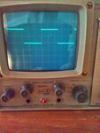
CRO.jpg

IT WORKED..

I placed the CRO on its side - the right side down - thinking what ever is obstructing is probably pushing to far left from the right side - banged the table and it move - happy days.

Banged the table some more - it moved some more - and now i have a trace that sweeps across the entire graticule.

Awesome - this trusty 37 year old+ CRO is still going strong.

thanks guys appreciate the help.

cheers


Joe
 

Status
Not open for further replies.

Part and Inventory Search

Welcome to EDABoard.com

Sponsor

Back
Top