Continue to Site

Welcome to EDAboard.com

Welcome to our site! EDAboard.com is an international Electronics Discussion Forum focused on EDA software, circuits, schematics, books, theory, papers, asic, pld, 8051, DSP, Network, RF, Analog Design, PCB, Service Manuals... and a whole lot more! To participate you need to register. Registration is free. Click here to register now.

Problems with lm338k

Status
Not open for further replies.

edwinvarghese

Junior Member level 1
Joined
Feb 27, 2014
Messages
17
Helped
0
Reputation
0
Reaction score
0
Trophy points
1
Activity points
127
I'm a newbie to analog circuit design. I'm doing a project of building a Robotic arm. The arm have a servo of 41KG/CM torque.
https://www.hobbyking.com/hobbyking...igital_servo_w_heat_sink_40kg_18sec_170g.html

I'm facing difficulties with designing the power supply for the circuit. Now m using LM338k for providing (output 7.2V) power for the servo in order to get more current I'm connecting output from 2 LM338K and a LM338p. The input to three regulator IC's are 12V/5A. I also tried the input with a 12v/7Ah battery still no help SERVO DOESNT TAKES THE WEIGHT(I'm not overloading the servo, m only giving half of its capable torque in my design but still it doesnt works) :(


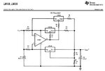
Can I use this for powering my servos??? If yes what should be the input current???

10A.png
15A.jpg

Someone please help me with this :( THANKS IN ADVANCE
 

The Chinese servo does not give a spec for its maximum current so it probably draws more current than you have.
The LM338 is not a generator. If three can produce an output of 15A then their input must total 15A, not 5A.
If the output of your circuit is 7.2V when it was powering the loaded servo then your circuit works perfectly but the servo is no good.

The LM307 is obsolete but the circuit needs an opamp like it that works with its inputs at the positive supply. Which opamp did you use?


First of all thank you sir for responding, The servo works fine under unloaded or minimal loaded condition the problem is with supply i guess. Now m not using op amp actually m using 3 Lm338K voltage regulator circuits and connecting their output parallel (so that current will add in the junction) , What is the difference between this method and op amp method????. And i think with what you said problem lies with my input power I'm only giving 12v/5A for three Lm338k's!
 
Last edited:

If you connect regulators in parallel then the one with the slightly higher voltage will power the load until its voltage drops when it becomes overloaded. Then the regulator with the next lower voltage powers the load until it becomes overloaded.
That is why an opamp is used to allow the regulators to share the current.

Simply measure the output voltage of your circuit when it powers the loaded servo to see what is happening. Its output voltage is probably dropping. Then simply measure its input voltage to see what is happening. The input voltage of the LM338 regulators must be 2V higher than their output voltage.
 
Sir, input is 12V which is around 4V higher than output voltage which is 7.2V. And You are right voltage is dropping i had checked that while testing :(

So in order to make a circuitry as shown above for 15A, resistors should be of which power rating?? Also 0.1 and 0.5 ohm resistors are available?? i did a search on Google but nothing useful returned
 

The power in a resistor is I squared x R where I is the current and R is the resistor value. So 5A in 0.1 ohms is 2.5W of heat. Use a 5W resistor.
0.1 ohms and 0.47 ohms are common resistor values.
For 0.05 ohms/10W use two 0.1 ohms/5W in parallel.
Where will you find the obsolete LM307 opamp? A more modern TL081 opamp will replace it.
 
Sir, the supply current should be 15 amps right ?? so why we are 0.1 ohms with 5A only????

And about 741 op amp, I don't know will it be available or not. Have to ask at the shop if they are not available then i will go for TL081
 

I think you have never looked at the datasheet of an LM338 adjustable voltage regulator.
The maximum output current is 5A. The 0.1 ohm resistors will have a voltage of 0.5V across them when their current is 5A. The voltage across the resistors allows the three LM338 ICs to equally share the total current of 15A.

Look on a datasheet of an old 741 opamp. Its inputs do not work if they are less than 3V less than the positive power supply voltage so it will not work in this circuit! This circuit was designed to use an old LM307 opamp that is obsolete and is not made anymore.

Then look at the datasheet of a TL081 opamp. Its inputs work perfectly when they are at the positive supply voltage like in this circuit.
 
Sir, I'm talking about R2 and R1 what should be power rating of those resistors? we are supplying 15A right so should they be 15*15*0.1 ???

And as i said I don't have any experience with such circuits, I haven't used any opamp till now so m totally unaware about their specs and all that :(
I will try to find TL081 op amp as you suggested. Is there are any other replacement for LM307? In case if i didn't got TL081??

- - - Updated - - -

Also the rating of R7,R8,R3 and R4...... would 3w will be sufficient for R3 and R4??
 

Sir, I'm talking about R2 and R1 what should be power rating of those resistors? we are supplying 15A right so should they be 15*15*0.1 ???
No. You did not look at the simple schematic.
R1 has the current of two 5A regulators in it. What is 5A + 5A=? each regulator needs 0.1 ohms so use two o.1 ohms/5W resistors in parallel to make 0.05 ohms/10W like I said in my post #6.

And as i said I don't have any experience with such circuits, I haven't used any opamp till now so m totally unaware about their specs and all that :(
I will try to find TL081 op amp as you suggested. Is there are any other replacement for LM307? In case if i didn't got TL081??
There are hundreds of opamps available here in The West that can be used. Since you might not be able to find an ordinary TL081 available everywhere here then I will not ask, "Can you find this one there? Can you find that one there?" Over and over.

Also the rating of R7,R8,R3 and R4...... would 3w will be sufficient for R3 and R4??
The datasheet for the LM338 shows that R7 always has 1.25V across it so its power dissipation is only (1.25V squared)/120 ohms= 0.013W. Any little resistor size is fine.
R8 is a pot that has the same current as R7 which is 1.25V/120 ohms= 10.4mA so the power dissipation of R8 is only (10.4mA squared) x 2k= 0.392W so use a 1W pot.
R3 and R4 also dissipate 0.392W so use 1W resistors because 1/2W resistors will be VERY hot.

I did not know that 3W resistors are available in your country. If they are used for R2, R5, R6 and two in parallel for R1 then since they dissipate a maximum power of 2.5W they will be VERY hot so I recommend using 5W resistors.
 
First of all thank you sir, I got TL081 :)
The trim pot i got is BOURNS-3386 T202 in which data sheet says it is capable of 0.5 watt will it be sufficient (even if it heats up it wont burn right) ?
I didn't got 2K/1W here so m using two 1K/2W in series to obtain 2K resistor.
and for 0.1 ohm i got fusible resistance that will be fine right? ( I'm from India here its not that easy to get electronic components )
I did not know that 3W resistors are available in your country
My mistake sorry..... As i said I'm new to all these kind of things.......
 
Last edited:

I got TL081 :)
Good.

The trim pot i got is BOURNS-3386 T202 in which data sheet says it is capable of 0.5 watt will it be sufficient (even if it heats up it wont burn right) ?
You and I did not calculate the value of the pot needed for an output voltage of only 7.2V. Its current will be 1.25V/120 ohms= 10.4ma and its value should be adjusted to only (7.2V - 1.25V)/10.4mA= 570 ohms which is less than half of 2k ohms so the part of the pot will be hotter than its rating and it will burn. If you use a 1k pot then it will be hot but it will not burn unless you turn down the voltage then it will burn.

I didn't got 2K/1W here so m using two 1K/2W in series to obtain 2K resistor.
Two 1/2W 1k resistors in series make a 1W 2k resistor. Use 2W resistors if you have enough space for them.

and for 0.1 ohm i got fusible resistance that will be fine right?
I have never seen it. You need 0.1 ohms 5%. A fuse is probably not 5%.
 
Last edited:
HCA.jpg

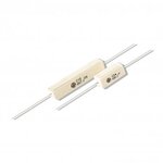
This is the resistance m talking about...

Okay i have 1k trim pot of 0.5 watt i will use them in circuit...

Two 1/2W 1k resistors in series make a 1W 2k resistor. Use 2W resistors if you have enough space for them.
I don't think I'm going to have a problem with space.....:)

Now m going to make the circuit hope things will go well :)

- - - Updated - - -

if i add a 1K/2W resistor series with 1K trim pot, the chances for trim pot to burn out will decrease????
 

The power resistors in your photo are marked "J" which is 5% and will be fine.

If you add a 1k resistor in series with a 1k trim pot then the minimum resistance is 1k ohms so the minimum output voltage will be 1.25V + (10.4mA x 1k)= 11.65V which cannot be produced from LM338 regulators that have a 12V supply.
You must THINK about how these simple parts work together.

In my post #12 I said that when the trimpot (without a series resistor) is 570 ohms then the output voltage will be 7.2V.
What is the lowest voltage you want?
 
7.2 volt i don't have to vary the output voltage....

And how I can modify the above circuit for 15A to produce 20A?? can we add one more LM338K in parallel????
I tried 10A circuit first then 15A circuit. movements are much smoother with 15A ckt than 10A. But still there is small problem a power supply of 20A will solve the problem :(

Upon giving one more LM338K output parallel to 15A regulator it works fine...... but as you said its not systematic way right...... so can we add one more LM338K to op amp without any additional circuitry??? If yes how will be circuit what all components i should need???
 
Last edited:

Sir, In order to make a 20A regulator if i add one more LM338K in parallel with the three in 15A circuit and change the resistance value R1 to 0.33 and adding a 0.1 ohm and 2k with the new LM338, will the circuit work ????
what will be the values for capacitors ? how they are calculated????
 

Sir, In order to make a 20A regulator if i add one more LM338K in parallel with the three in 15A circuit and change the resistance value R1 to 0.33 and adding a 0.1 ohm and 2k with the new LM338, will the circuit work ????
No, because then the opamp will be overloaded.
 
What about adding output from one separate LM338K parallel to the output of 15A regulator???
Is there any way to distribute load equally????
 

and about that 1k trimpot If add a 120 ohm 1/2 or 1/4 with that trim pot it will work fine right???
still its working but heating up a bit
 

The opamp distributes the load equally to the three LM338 regulators. You can add a PNP emitter-follower transistor like a TIP32 to the output of the opamp inside its negative feedback loop, then many regulators can be used.

- - - Updated - - -

and about that 1k trimpot If add a 120 ohm 1/2 or 1/4 with that trim pot it will work fine right???
still its working but heating up a bit
I said that a 2k 0.5W trimpot will burn when it is turned down to 570 ohms with a current of 10.4mA.
If you use a 1k 0.5W trimpot and turn it down to 570 ohms then it will be warm and will be fine.
 
Status
Not open for further replies.

Similar threads

Part and Inventory Search

Welcome to EDABoard.com

Sponsor

Back
Top