Continue to Site

Welcome to EDAboard.com

Welcome to our site! EDAboard.com is an international Electronics Discussion Forum focused on EDA software, circuits, schematics, books, theory, papers, asic, pld, 8051, DSP, Network, RF, Analog Design, PCB, Service Manuals... and a whole lot more! To participate you need to register. Registration is free. Click here to register now.

Power Supply Failed - Samsung Plasma PS-42Q96HD

Status
Not open for further replies.

dailafing

Newbie level 3
Joined
Mar 2, 2014
Messages
3
Helped
0
Reputation
0
Reaction score
0
Trophy points
1
Activity points
32
There are so many posts online about how Samsungs were identified by the ticking or clicking relays, and everyone said it was almost always a bulging cap, or failing that it was a MOSFET...

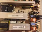
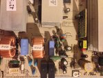
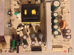
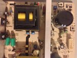
Well, my Samsung has just joined the fun, but I was surprised to find that upon disassembly, everything looks fine to me...

No dry joints, or missing solder...
No bulging caps...
No scorching or burning
No cracked resistors or anything..

In fact, by my eye, visually everything is find save for some cobwebs and dust...

So I'd like to kindly refer to the experts here, and ask for a second opinion.
ideally I don't want to have to un solder everything and test it manually, because
1) its a pain, and
2) I don't really know what I'm doing.

I know how to be safe, and I've had my initiation when working on a live iMac pranging myself with 240v to earth via my chest
(Right hand earthed by holding metal LCD bezel, and left knuckle touching live 240v feed)

Please see video and pictures of my power board, (BN44-00162A, PSPF531801A, W2A)

Thanks

I did a 720p YouTube video passing over the circuits Here:
http://youtu.be/4R4cOi2Yr04

**broken link removed**

**broken link removed**
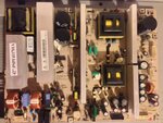
image.jpg

image.jpg

image.jpg

image.jpg

image.jpg

image.jpg

 
Last edited:

The capacitor that normally fails on these type of boards is a 1500uF 35V capacitor located at the right hand side of the board, I check the ESR of the capacitors incircuit, but if you don't have a ESR meter one trick is to remove the suspect capacitor and put it across a power supply and measure the leakage current at its maximum rated voltage, the leakage is normally proportional to the ESR of the capacitor. Just because the capacitors don't bulge does not mean that they are good.

Hi there, I had an email saying you had also asked why I thought it was the power supply. But I can't find the part of your message on the forum. Did you remove it because of the fact that the TV is making the relay clicking sound, typical of the Samsung TV issue that is known?
Basically, could it possibly be another part of the TV, might it not be the power supply after all?

Could you explain a little more about how I may test the capacitors without an ESR meter?
I have a standard multimeter which measures voltage and ohms. Am I able to use this to measure capacitance in some way? What figures would I be looking for on the suspect capacitors, since I've never measured capacitance before I'd really appreciate your help understanding the figures I would be looking at.

I would describe myself as an amateur, but I am confident with electronics because I'm quite careful and do my research before going to far.
Also, could you take my pic of the board and highlight in Windows paint which capacitors you believe are the ones I should check first?

In relation to testing the voltages, I believe my multimeter should be able to do the job. However would i test for this whilst the power supply is connected to the TV and powered up? It sounds like a daft question, but I can't see any immediate reason why not, I'm looking for clarification from the experts.

I really appreciate your help, thank you so much.
 
Last edited:

Testing the ESR of a capacitor without a ESR meter.

I have found that a capacitor with a high ESR also shows a high leakage current when the rated voltage is applied across it, so if you have no way of measuring the ESR of a capacitor, then putting the suspect cap across a power supply set at the rated voltage and measuring the leakage current is a good indication of its ESR. The current should not be more than a few milliamps for a good capacitor once the initial charge current has stopped.
The buffer boards are the small boards down the left hand side of the TV (looking in the back) which connect to the 'Y; board.

The capacitor that usually fails on the Samsung power supply boards is the 1500uf 35V one.

I removed the comment about measuring voltages because I reread you description and realized that you could not do so.

The fault may not be with the power supply at all, the second most common fault on a plasma screen is for a buffer board to go short which causes the 'Y' board to fail, which will make for an expensive repair, this can also cause the power supply to trip.
 

Lots of pictures, but what exactly is the problem?


There are so many posts online about how Samsungs were identified by the ticking or clicking relays, and everyone said it was almost always a bulging cap, or failing that it was a MOSFET...

Well, my Samsung has just joined the fun, but I was surprised to find that upon disassembly, everything looks fine to me...

No dry joints, or missing solder...
No bulging caps...
No scorching or burning
No cracked resistors or anything..

In fact, by my eye, visually everything is find save for some cobwebs and dust...

So I'd like to kindly refer to the experts here, and ask for a second opinion.
ideally I don't want to have to un solder everything and test it manually, because
1) its a pain, and
2) I don't really know what I'm doing.

I know how to be safe, and I've had my initiation when working on a live iMac pranging myself with 240v to earth via my chest
(Right hand earthed by holding metal LCD bezel, and left knuckle touching live 240v feed)

Please see video and pictures of my power board, (BN44-00162A, PSPF531801A, W2A)

Thanks

I did a 720p YouTube video passing over the circuits Here:
http://youtu.be/4R4cOi2Yr04

**broken link removed**

**broken link removed**
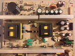
View attachment 102752

View attachment 102753

View attachment 102754

View attachment 102755

View attachment 102756

View attachment 102757


Hi,
I wouil like to suggest testing the Shottky dual rectifier that is located near the capacitors. You can test them with a multimeter on the ohmimeter range usually 2K (for diodes). Put negative prod on the center pin and mesure the other two pins. Sometimes this component is tricky. Mesure twice.

Narciso Peleida
 

Status
Not open for further replies.

Part and Inventory Search

Welcome to EDABoard.com

Sponsor

Back
Top