Welcome to our site! EDAboard.com is an international Electronics Discussion Forum focused on EDA software, circuits, schematics, books, theory, papers, asic, pld, 8051, DSP, Network, RF, Analog Design, PCB, Service Manuals... and a whole lot more! To participate you need to register. Registration is free. Click here to register now.
Yes, it helps if you give your specification first.
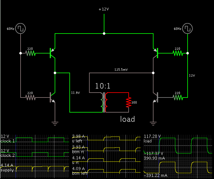
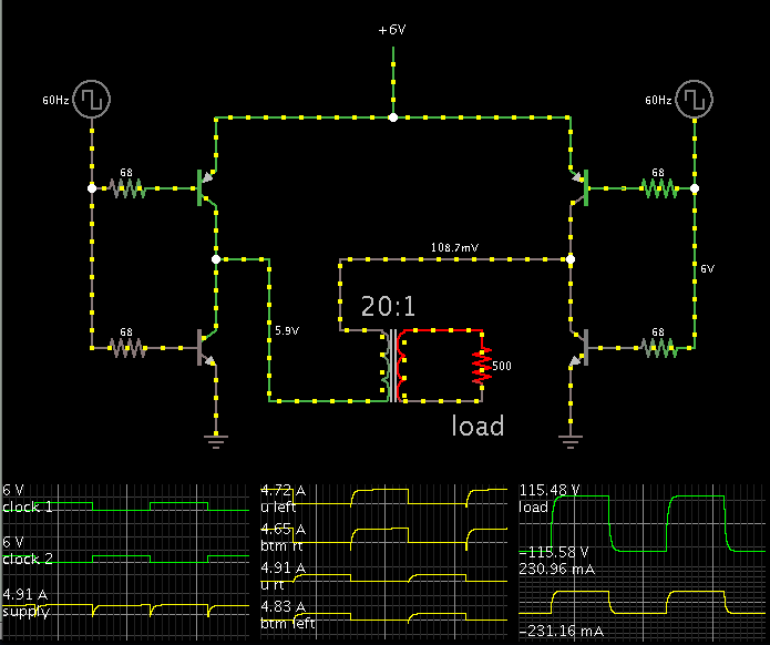
Notice the scope traces show the load gets 115 V at 231 mA. This is 26W.
In this simplified configuration the inverter will automatically draw sufficient power from the supply. In order for this to happen, it requires that your transformer has the proper step-up ratio. It also requires that you bias the transistors sufficiently (if you use transistors).
In a few cases the converter will adapt to your load. It is usually not this easy of course.
You must determine what ratings the components need to have.
The simulation shows the transistors getting 76 mA bias current. You will need to choose robust power transistors, if you don't want them to be destroyed. Your driver circuitry (clocks) must be able to apply sufficient bias current to the transistors.
Or if you use mosfets they must be the kind that can turn on full, in response to a low supply voltage (6 V).
The transformer must be designed to:
* step up 20 X
* operate at 60 Hz (or 50 Hz, if your appliances are made to run on that)
* handle 5A incoming without saturating
* provide 30W output
As I experiment with simulations, it appears a suitable Henry value for the primary is 40 to 400 mH. The transformer size will be a couple inches on each side.
This inverter produces square waves. If you want sine waves, then the driver circuitry will be more complex.
This site uses cookies to help personalise content, tailor your experience and to keep you logged in if you register.
By continuing to use this site, you are consenting to our use of cookies.