igeorge
Member level 5
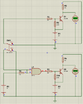
The circuit in the attached is strange
In the top is the same like in the bottom, but the to circuit act normal switching on and off -see the values on the voltmeters
the one in the bottom, never switch off, and is contently on
The voltage on the base is changed as you can see the logic dots - red = 1 blue = 0
I need an explanation how to do it because i will switch the transistor from a logic gate
Thank you
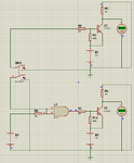