Continue to Site

Welcome to EDAboard.com

Welcome to our site! EDAboard.com is an international Electronics Discussion Forum focused on EDA software, circuits, schematics, books, theory, papers, asic, pld, 8051, DSP, Network, RF, Analog Design, PCB, Service Manuals... and a whole lot more! To participate you need to register. Registration is free. Click here to register now.

Which core area value gets used when gapping ferrite core?

Status
Not open for further replies.
T

treez

Guest
Hello

I have just calculated that a 1.25mm gap in the centre post (only) of the following core......PQ50/50-3C96

...will give an inductance of 341uH with 33 turns, and the saturation current will be 9A7.
(considering 0.3T = saturation)


However, i used the Effective core area (Ae) in the calculation and not the minimum core area (Amin).

...Is this correct, or do i need to use the area of just the centre post, where the gap will be?

PQ50/50-3C96 datasheet:
https://www.ferroxcube.com/prod/assets/pq5050.pdf


I do this by calculating reluctance via Rel = length/(u0.ur.A), then L = N^2/Reluctance

...i calculate reluctance of ferrite and gap then add them ....but which Area value gets used for core and air gap?
 
Last edited by a moderator:
The usual gap calculation doesn't use core area at all, just effective length and permeability, see Ferroxube data book. An accurate calculation would need to consider both acutal gap area and stray flux. At the end you have to refer to a 3-D magnetic simulation. Do you really need it?

Curiously PQ50 isn't offered as a gapped core by Ferroxcube. Are you going for custom made parts?
 
  • Like
Reactions: treez

    T

    Points: 2
    Helpful Answer Positive Rating
Hello,

Yes i am doing custom gap as there is nothing this big with a gap.

I thought with gapping you have to go by the reluctance, and reluctance = length/(uo.ur.A)

..where "A" is area......i dont see how you can do it wothout the area......the gap has an area, its not just a gap anywhere....its in a particular area of core cross section?
 

Did you review the Effective Permeability point in the Ferroxcube Soft Ferrites and Accessories data book? It's on the first introduction page.

P.S.: In case of a small gap,e.g. 0.1 mm, it would be correct to put-in the ratio of air gap to effective area in the calculation. But with 1.25 mm, you should be primarly concerned about a correction for the fringing flux. There's a calculation of effective permeability with fringing flux in Soft Ferrites by Snelling, but it's rather long winded.
 
Last edited:
  • Like
Reactions: treez

    T

    Points: 2
    Helpful Answer Positive Rating
Thanks, i read that databook, i wonder how you can know that a 0.1mm gap is ok, but a 1.25mm gap is not ok?
 

It's just an estimation. According to the empirical formulas given by Snelling, the effective air gap radius will be larger than the pole radius by about 1.6 mm in the present case. That's an area increase of 35%. At 0.1 mm air gap, it's only 4 %.

The effective air gap radius increment is given as (0.241 + 0.318 ln(ba/lg))lg with lg as air gap length and ba as length of the limb containing the air gap.
 
  • Like
Reactions: treez

    T

    Points: 2
    Helpful Answer Positive Rating
Thanks FvM,

The PQ5050 datasheet is in first post,

Would you say that length of limb containing the air gap is 36.1mm in the PQ5050 case (the air gap will be in the centre post)

...From what you kindly say, it appears to me that an "effective reluctance" of a larger air gap can be calculated, and this then used in the overall reluctance calculation.?

In any case it looks to me that fringing makes the air gap reluctance less than it is calclated by the " normal" method that applies with smaller air gaps?

...also, please can you tell what is the "pole radius"?
 
Last edited by a moderator:

In any case it looks to me that fringing makes the air gap reluctance less than it is calclated by the " normal" method that applies with smaller air gaps?
The effective air gap area will be always increased by fringing flux respectively the reluctance decreased. The question is about order of magnitude. Even 0.1 mm air gap has 4 % reluctance reduction according to Snelling.

what is the "pole radius"?
You call it "center post", the radius is 10 mm, presently.
 
  • Like
Reactions: treez

    T

    Points: 2
    Helpful Answer Positive Rating
Thanks,

It seems to me quite amazing that the "length of limb containing the air gap" comes into the equation.

How does the magnetic flux "Know" that its in a limb?.....surely it just sees the entire core volume as one lump of ferrite?.........

It means that "squat" cores with a low centre post length , but having the same path length, would suffer less increase of area of the air gap......it some how does not seem intuitive?
 

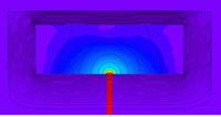
The intuitive point is that the limb length decides (in a logarithmic scale) how far the air gap flux extends to the side. Of course I can't verify the relations in Snelling's book. But you can see from a field simulation that some flux lines are actually spanning the whole limb. (The axial-symmetric simulation is only showing half of the core)

 
  • Like
Reactions: treez

    T

    Points: 2
    Helpful Answer Positive Rating
The effective air gap radius increment is given as (0.241 + 0.318 ln(ba/lg))lg with lg as air gap length and ba as length of the limb containing the air gap[/QUOTE

....i trialled out this formula with the Epcos ETD 54/28/19 core:
**broken link removed**

...this datasheet , above, gives AL values for N87 material, both ungapped and with a 2mm gap.

By the given AL value of 229 (for a 2mm gap) its evident that 66 turns are needed to give 1mH (with the 2mm gapped N87 core)

.......The method calculated using Snellings equation, (quoted above), makes it 61 turns to give 1mH with the 2mm gapped core (incorrect by 5 turns)

........The simple way, which takes no account of fringing fields, makes it 75 turns to give 1mH with the 2mm gapped core. (incorrect by 9 turns)


...So Snellings adjustment of airgap area has improved the accuracy, but , to be honest, as you can see, its really not too accurate at all.
...dop i have to buy a 3D magnetic simulator for thousands of pounds to get an accurate way of calculaing this?
 
Last edited by a moderator:

You can spend lots of money and time into a SW package, but if the machining is cheap for you just give it a try and measure the inductance, If too high, you need to increase the gap. Final adjustment can be done with plus or minus a turn.

Note that due to the stray field around the gap you will get eddy current loss in the copper near the gap. That additional loss can be large. also note that when you keep the windings away from the gap, the loss reduces, but the stray field around the core increases. this may affect other circuitry.
 
  • Like
Reactions: treez and FvM

    FvM

    Points: 2
    Helpful Answer Positive Rating
    T

    Points: 2
    Helpful Answer Positive Rating
By the given AL value of 229 (for a 2mm gap) its evident that 66 turns are needed to give 1mH (with the 2mm gapped N87 core)

.......The method calculated using Snellings equation, (quoted above), makes it 61 turns to give 1mH with the 2mm gapped core (incorrect by 5 turns)

........The simple way, which takes no account of fringing fields, makes it 75 turns to give 1mH with the 2mm gapped core. (incorrect by 9 turns)
I got a smaller difference (AL of 213 nH) by applying Snellings correction and the simplified effective µe calculation. But in any case I agree with WimRFP that you should determine the real inductance empirically.
 
  • Like
Reactions: treez

    T

    Points: 2
    Helpful Answer Positive Rating
WimRFP:
Note that due to the stray field around the gap you will get eddy current loss in the copper near the gap. That additional loss can be large.

Thanks, can this be quantified for eg the ETD54/28/19 core above with the 2mm gap?

Thanks FvM, sorry i for got to use the ue correction....ill go back and re-do
 

I am not aware of something easy applicable regarding eddy current loss in the gap area.

I did experiments with gaps in the mm range (thick wires/strips, in combination with E cores with air gap in the center leg only) and the additional loss due to the windings close to the gap contributed in the 50% range of the total loss. using the outer (non-gapped) legs did reduce the loss significantly, but increased the stray field to such high values that nearby PCB ground plane became warm (so some clearance was required).

If it is an inductor (so no transformer) you may fill the coil former with insulating material before actual winding so that there is no copper close to the gap.

Also here I think experimentation will give you the hard figures. With such large air gaps, actual inductance depends on where you put the windings.
 
  • Like
Reactions: treez

    T

    Points: 2
    Helpful Answer Positive Rating
FvM,

for the simplified ue calculation, do you mean that on equation 5, on page 7 of the Ferroxcube Soft Ferrites and Accessories data book?

Ferroxcube Soft Ferrites and Accessories data book:
https://www.ferroxcube.com/appl/info/HB2009.pdf

...i trid that euation 5, along with Snellings correction that you kindly gave above, and i am not getting a realistic answer, so i wonder if i've missed something.......it came out as 96 turns to get 1mH with a 2mm gap.....when the datasheet for ETD54 makes it 66 turns.

The "ue" value from page 7 comes out at just 60.2, which seems very low indeed?
 

I repeated the calculation and got similar too high µe values as you reported in post #11. The only plausible reason is that I misunderstood Snellings explanation of the factor "ba" (respectively the explanation is wrong,as you prefer). If you don't understand "ba" as the length of the limb (center post/pole) containing the air gap but as distance between center and outer part of the core, the calculation fits quite well. I get a µe value of 83. Instead of the min/max dimensions in the Epcos datasheet, you should use the typical dimensions (as given e.g. in the Ferroxcube databook).

The question about the right ba value continues your comment in post #9 about it's physical plausibility. I must confess, that I tended to the other (lateral distance) interpretation first, because it sounded more plausible to me, but I found the description pretty clear, so I accepted the limb length reading.

P.S.: Although it's apparently possible to achieve a good fit of the effective µe calculation with datasheet values (by trial and error method, unfortunately), I would follow the suggestion to build a prototype coil with a handcrafted air gap. Even if the inductance value can be predicted (it's still questionable for different copper fill factors and forms), the losses hardly can.
 
Last edited:
  • Like
Reactions: treez

    T

    Points: 2
    Helpful Answer Positive Rating
FvM
Even if the inductance value can be predicted (it's still questionable for different copper fill factors and forms)

.....thanks, i believe you are suggesting that there is no fixed equation that we can just use too always calculate the new total reluctance of a gapped core....because the equation would have to very depending on the core's form?...(eg whether PQ, RM, ETD etc etc)

.....anyway, taking the lateral distance , as you above describe gives a pretty respectable answer for the ETD54 core.........(62.6 turns for 1mh versus actual 66 turns)

so im going to do it by emperical means, but with that bit of help your equation gives..


.....i just dont want to be doing it in this kind of trial and error way, and then the boss will ask, "why arent you calculating it?"

....i think after our discussion, its seen that this really is not an exactly calculable thing?.....
 

.....anyway, taking the lateral distance , as you above describe gives a pretty respectable answer for the ETD54 core.........(62.6 turns for 1mh versus actual 66 turns)
It gives 66 turns in my calculation.

I agree about the problem with not-rotational symmetric core shapes. They demand for an estimation.

The main limitations are however in the other factors mentioned by WimRFP. So if the problem is about ordering a larger number of custom made core sets, getting a prototype either from the manufacturer or making it yourself, is strongly suggested.
 
  • Like
Reactions: treez

    T

    Points: 2
    Helpful Answer Positive Rating
Status
Not open for further replies.

Similar threads

Part and Inventory Search

Welcome to EDABoard.com

Sponsor

Back
Top