Continue to Site

Welcome to EDAboard.com

Welcome to our site! EDAboard.com is an international Electronics Discussion Forum focused on EDA software, circuits, schematics, books, theory, papers, asic, pld, 8051, DSP, Network, RF, Analog Design, PCB, Service Manuals... and a whole lot more! To participate you need to register. Registration is free. Click here to register now.

current transformer circuit for measuring current

Status
Not open for further replies.

zia

Full Member level 5
Joined
Sep 24, 2010
Messages
284
Helped
27
Reputation
54
Reaction score
26
Trophy points
1,318
Location
Islamabad Pakistan
Activity points
2,746
hi i m required current transformer circuit for measuring current for energy meter
may anybody help
 

you buy current transformer & then you interface with precision rectifier.
 

can pls rate the current transformer in consideration and also the power rating at which you are using this device
 

What is the amount of power or ampere did you want to measure??
 
  • Like
Reactions: fmtech

    fmtech

    Points: 2
    Helpful Answer Positive Rating
i want to measure upto 5Amp max and i have ct but i dont have accurate circuit
 

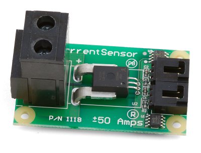
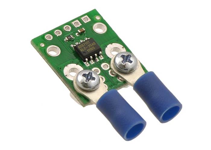
try allegro sensor which have a linear response
**broken link removed**
 

i want to measure upto 5Amp max and i have ct but i dont have accurate circuit
AC OR DC CURRENT?
AC: means that you can use current transformer (and it is cheap and simple)
DC: means that you must use Hall effect sensor or shunt resistor (resistor is preferred if your system is not isolated)
 

Zia You didnt specify which type of electron current You want to measure, alternative or directed ?
 

next several solutions are possible post your schematic and the type of current you are using AC or DC
 

You can use Hall sensor for AC current or Current Transformer.

Measuring Mains Current Doesn't Have To Be Difficult
**broken link removed**

**broken link removed**
 
Last edited:

1118_0_Web.jpg


1129_ASC711%20current%20sensor%20carrier%20with%20solderless%20ring%20terminal%20connectors%20%28not%20included%29.jpg


https://www.robotgear.com.au/Cache/Files/Files/166_ACS711_datasheet.pdf


Hi Zia

U can use the Hall Effect Sensor For Measuring the Current Passing through the coil winding...
This will produce the magnetic flux according to increasing Load on this coil line inserted to the Sensor Field..
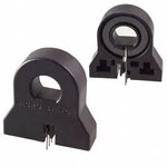
images.jpeg
 

if you ratio between no. of winding in secondary & no. of winding in primary, proportion the output to be taken as current.
 

need some necessary information, e.g.input current and output current, input winding is 1 turns normally, so that can calculate turns of secondary winding, accurate degree, e.g. 0.5 or 0.2, and dimension, so that select core.
 

still you say current and all are posting based on the conception that it is a AC supplyu

give us much clearer idea about it
 

Since you're going to be using it for energy meter, precision is required. So, you should get a good-quality current transformer or a half-effect sensor. Then, you can get accurate readings.

One simple method is to use a shunt and a regular 50Hz transformer across the shunt to get output and then measure from the output. However, this is probably not going to be very accurate and may not be good enough for an energy meter.

Hope this helps.
Tahmid.
 

Status
Not open for further replies.

Similar threads

Part and Inventory Search

Welcome to EDABoard.com

Sponsor

Back
Top