Continue to Site

Welcome to EDAboard.com

Welcome to our site! EDAboard.com is an international Electronics Discussion Forum focused on EDA software, circuits, schematics, books, theory, papers, asic, pld, 8051, DSP, Network, RF, Analog Design, PCB, Service Manuals... and a whole lot more! To participate you need to register. Registration is free. Click here to register now.

High voltage astable multivibrator problem

Status
Not open for further replies.

Artlav

Full Member level 2
Joined
Nov 26, 2010
Messages
144
Helped
2
Reputation
4
Reaction score
2
Trophy points
1,298
Activity points
2,723
Hello.

I'm trying to make an oscillator that would run from 200V range, providing about 1 kHz with minimal current drain.
I started with making a test one that would fit the parts i had on hand and to check the theory.

The transistors are ksp44, apparently with Vcesat=0.4V, Vbesat=0.75 and gain of 40 to 200.
Now, if i understand this right:
Ic=1mA
C=500pF
Rc=(V-Vcesat)/Ic=199KΩ
R=(V-Vbesat)/(Ic/gain)=19.925MΩ
f=1/(1.386*C*R)=72Hz

Thus, the rounded up result:
hvosc.png


However, this circuit have two problems.
First, it oscillates at about 700Hz, not 72.
Second, it only peaks to 90V at collectors, not 190.

So, the question is - what did i do wrong?
Transistor's datasheet only lists ratings at 10V, can they be wildly different at 200V?

Secondary question - is there a better kind of oscillator to get 1kHz at 200V with less than 1mA of consumption?
With smaller capacitors needed for kHz range this kind of circuit stops working at all.
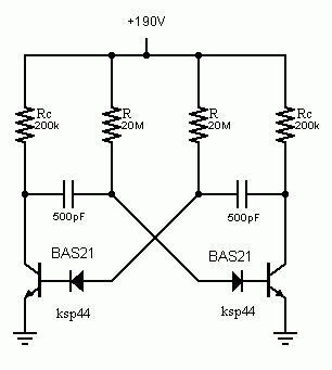
 

The negative Vbe voltag is cut by Vbe reverse breakdown, thus the effective RC time constant decreases considerably. Vbe breakdown possibly creates a lifetime problem for the circuit. You can e.g. add base series diodes with sufficient voltage capability.

Your caluclation assumes a minimal current gain of 100, although it can be as low as 40.
 

Using your frequency formula 1/(1.386 x 200K x 500pf) gives a result of 7215Hz.

The basic flaw in your design is that you ignore the leakage current into the transistor base pin, which is significant when the bias resistor is 20M and the fact that each transistor doesn't fully saturate or turn off before the other one halts it from doing so. It would be better to use an extra transistor in the circuit, firstly rescale the values in the present design so it runs off say 10V, this will overcome the leakage problem because the resistors will be much lower in value and the capacitor will be a more managable value for low frequencies. Then connect the emitter of one of the transistors directly to the base of a a high voltage transistor, connect it's emitter to ground and it's collector to +190V through a resistor. You can use lower voltage transstors for the oscillator stage and if necessary use a simple zener diode and resistor to stabilize the lower voltage supply for them.

What should happen is the current being switched from side to side of the multivibrator will chop the base current in the new transistor and turn it on and off far harder than at present. Note that the collector resistor and any load capacitance will cause the sharpness of the edges of the waveform and possibly it's amplitude to be reduced.

Brian.
 

The calculations look correct. Perhaps there is a problem with leakage current in the transistors, but I don't think that would explain the change in frequency.

I already explained the problem. You can observe the effect in simulation, if you set a realistic base reverse breakdown voltage (e.g. 7 - 10 V) in the transistor model (often set to infinity by default). Leakage current may add, but in't necessary to explain the issue. According to the transistor data they are small.
 

Dear Artlav
Hi
Why that way ? i understood that you want a square wave with high amplitude , let me guide you in simpler way :
Create an independent square wave with a not gate or a A stable with lower amplitude such as 5 or 15 volts then drive a mosfet with it ! you can achieve voltages above this value simply if use this way .
Best Wishes
Goldsmith
 

It should work better this way (diodes must be high voltage low leakage)

37_1341582126.gif
 

betwixt idea with lower voltage oscillator works rather well - i got 12V with a zener, and there is a square wave at 12V.
However, the HV transistor being fed from the emitter is producing a signal about as square as a circle, and at 60V or so. 100kΩ resistor above it.
Have i missed something?

goldsmith, details please.
I can't find a way to use one MOSFET to produce AC.
The whole idea of turning DC into AC of the same voltage is ungooglable - only stuff i can find is with a transformer bound in it, so i'm improvising wildly already.
And i haven't worked with MOSFETs enough to improvise.

What i want to get is a DC to AC converter to feed a voltage multiplier, kind of like this only from 200V:
ups.png
 

Ok, it looks like the current into the new transistor isn't sufficient to drive it hard enough. With a 1mA limit I suppose that's understandable.
Goldsmiths idea has merit, you might be able to use a high voltage MOSFET but using the existing oscillator. Try grounding it's source pin and connecting the gate to one of the transistor collectors, the drain still going to high voltage through a resistor. Being voltage operated, the MOSFET will not load the oscillator as much.

You should note that the voltage multiplier likes to be driven from a low impedance so 100K in series with it's input feed will hamper it's performance. It will work but it might take a long time for the voltage to maximize.

Brian.
 

It should work better this way (diodes must be high voltage low leakage)
1N4007s are the only things i had that fit the voltage requirements.
With 50pF capacitors they turn 40V sawtooth at 10kHz into 90V square wave at 700Hz all right.
Frequency now match the prediction.
Remaining issue - why only 90V?
Because 1N4007 have 50 times the reverse current than the one you specified, or something else?
 

What i want to get is a DC to AC converter to feed a voltage multiplier, kind of like this only from 200V:
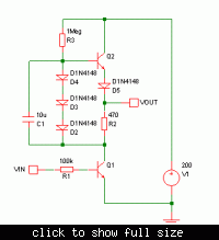
It will be a lot easier if you drive the voltage multiplier with a "totem pole" type of amplifier like the one below. There's two main advantages:
a) It only requires two NPN transistors.
b) It can be driven by a 5V pk-pk square wave e.g. from a 555 oscillator.

P.S. It should give a decent 200V pk-pk square wave at the output.


It will be a lot easier if you drive the voltage multiplier with a "totem pole" type of amplifier like the one below.
Nice, that works.
Most current with R1=200k, driven by the 200V native oscillator with diodes, as in FvM's last post.

However, the current loss is significant.
The input is about 6mA, AC output is about 1.5mA, or 3mA at 50% duty cycle, oscillator consumes ~1mA, where are the other 2mA?
Or is efficiency of 50% normal for this kind of thing?

- - - Updated - - -

Actually, no.
I just forgot the C1 capacitor.
With it the output current almost doubled, and now everything seem to add up.

Thanks for help everyone.
 

Status
Not open for further replies.

Part and Inventory Search

Welcome to EDABoard.com

Sponsor

Back
Top