Vermes
Advanced Member level 4

Assumptions:
This computer power supply was designed as an alternative source of energy to battery supply.
It was made of Codegen 350W power supply, model 300XX, placed in housing Z17 237x218x92.
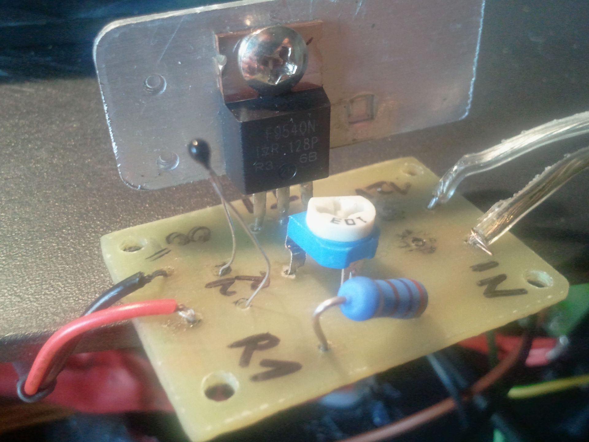
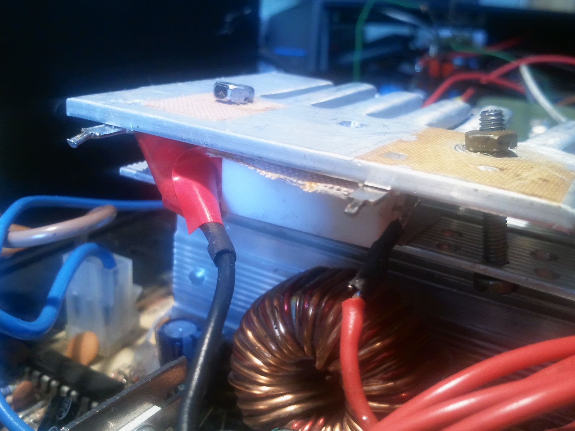
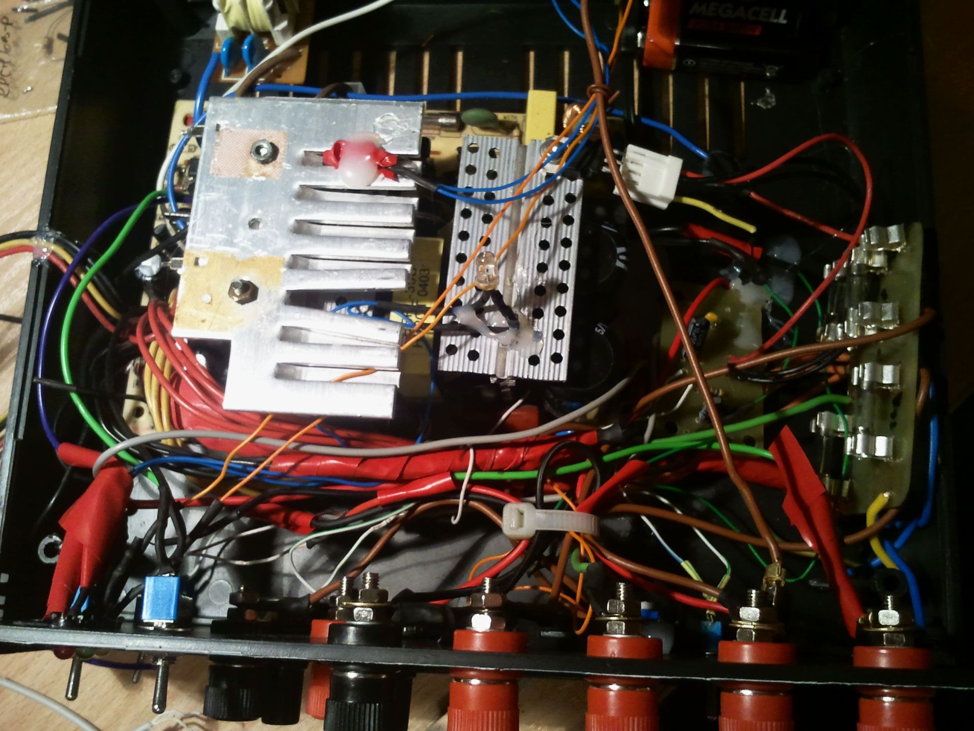
Voltages on each line are slightly lower than nominal, but they are within the tolerance for ATX power supplies. The main system is ATX with artificial load resistors attached between two heat sinks, which provides very good heat dissipation. In addition, fan 120x120 (supplied by voltage 17V[-5V and 12V]) is controlled by a simple system on IRF9540 with a thermistor on heat sink. Unfortunately, the fan does not fit the housing.
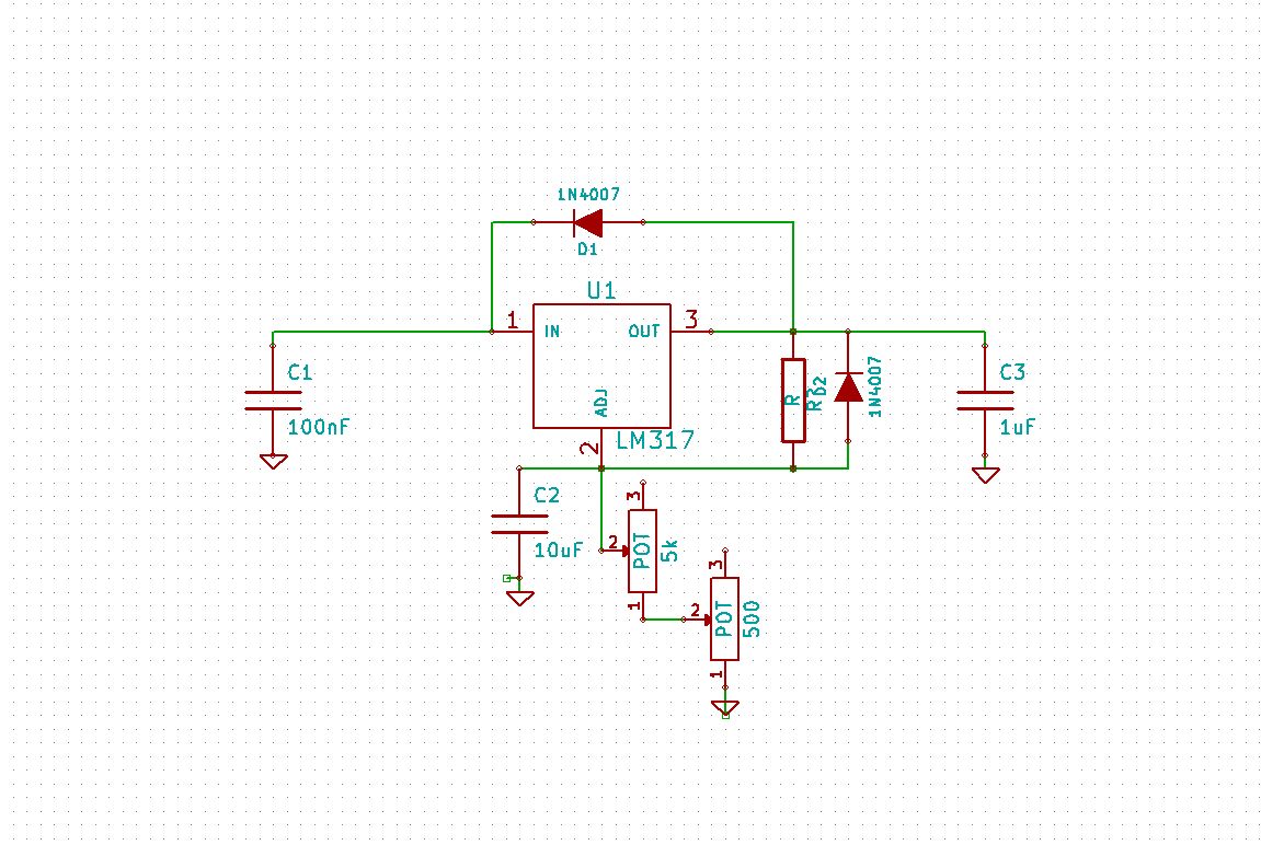
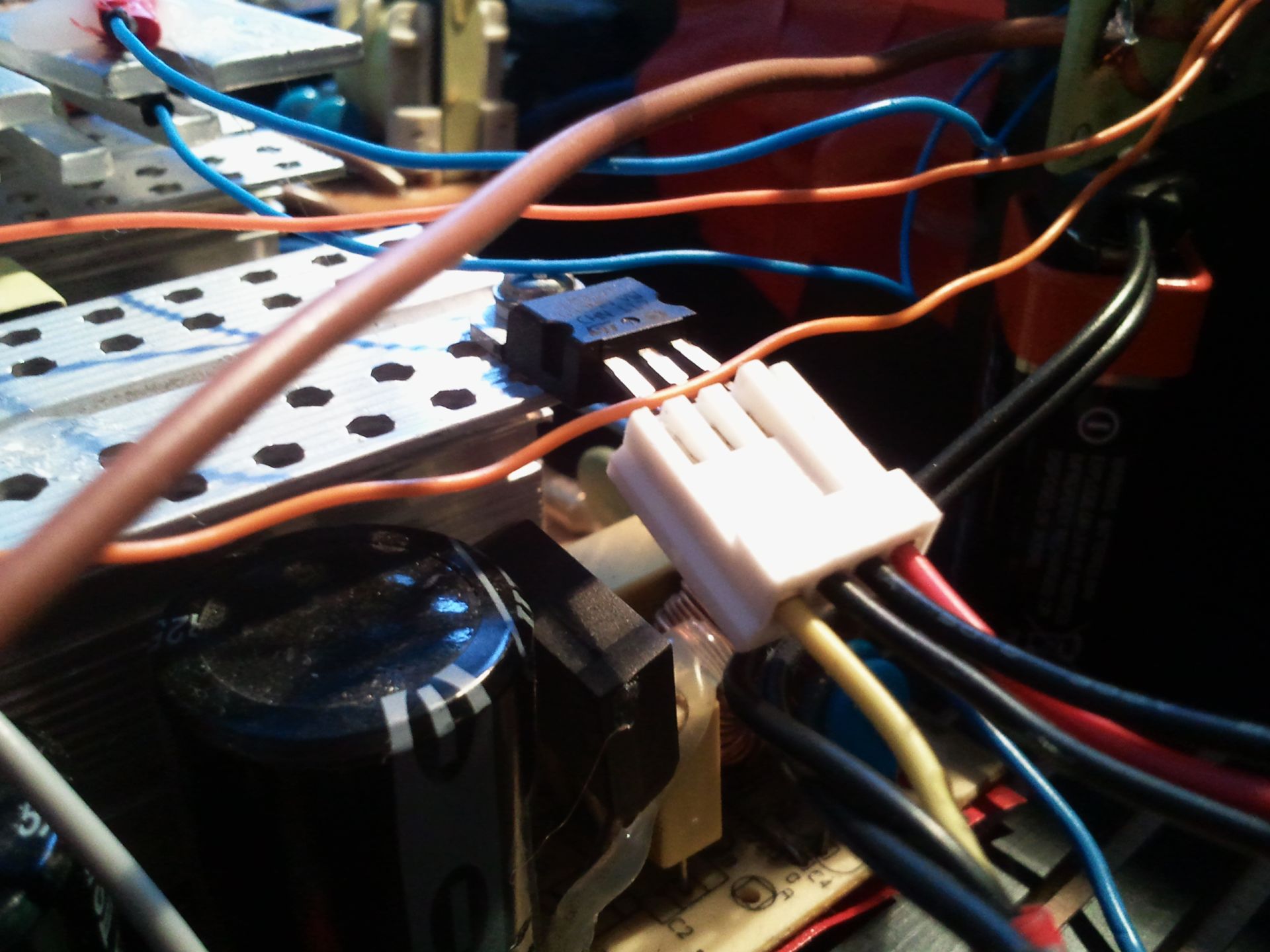
LM317 is attached to the second heat sink. It can be broken, so it is good to connect it to the system by an old plug, so in case of damage – it can be quick and easily changed.
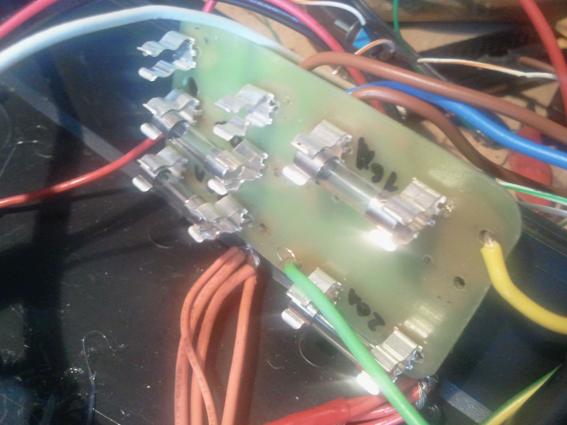
Except the internal protections, there is a board with fuses added to each line. Most of them is mounted to the housing using hot glue.
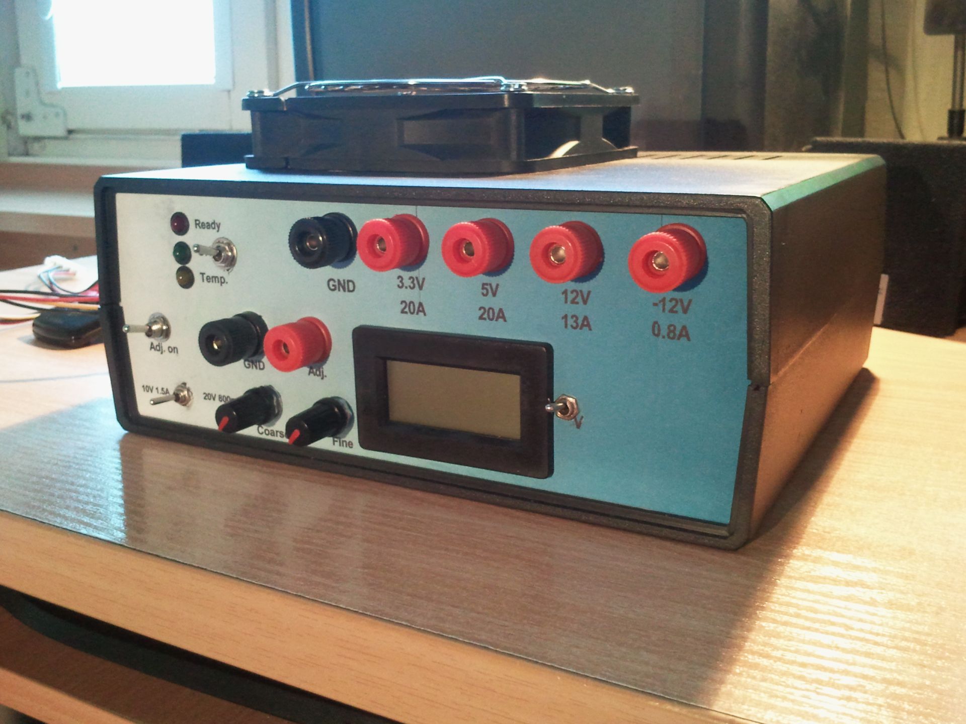
Front panel:
Background is made of self-adhesive paper. It was designed in Front Designer. You can see on it LEDs indicating the operation, banana socket for ATX power supply voltages, power supply output switch, adjustable output switch, range selection, panel voltmeter with a switch, voltage adjustment (rough and careful) potentiometers and banana sockets of adjustable output. There are two molexes derived on the side of power supply, which are useful for fast testing disks etc.
Range can be set by switching between the ground and line -12V, line 12V is connected permanently. Voltmeter indications are a bit biased on the video, but after calibration they are perfect. The voltmeter is powered from a 9V battery (it must have a separate voltage source).
Video:
Pictures:


Link to original thread - Zasilacz warsztatowy, przeróbka zasilacza ATX, regulator napięcia na LM317