tvibakar
Newbie level 4
- Joined
- Jul 2, 2012
- Messages
- 5
- Helped
- 0
- Reputation
- 0
- Reaction score
- 0
- Trophy points
- 1,281
- Location
- Chennai, India
- Activity points
- 1,356
Dear Sir,
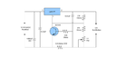
I am using 12V 7.2Ah Amaron Quanta lead acid battery for an Emergency Lamp. I am using the following charging circuit which is attached with this post. In this charging circuit, 230 ac voltage is given as input to the 16-0-16 transformer. The output of transformer is filtered through rectifier diodes and then given as input to the LM317 of charging circuit. As of now transformer is needed to step down the ac input voltage. I need a charging circuit without a transformer. So kindly suggest me a circuit which consists of input rectification without a transformer. Please suggest it with a moderate cost. And also I need one more clarification. I am using "Constant Voltage" - trickle charging method to charge the battery. I am using a load of 2 lamps of 110 W lamps which stand for around 50 minutes of full charged battery. The lamps will cut-off at 9.5-9.8 V. Then it takes around 16 hours to make the battery full charge. Could you please confirm me if I can charge the battery soon (min 6 hours). Is so at what rate I should use the load. Please help me in this situation.
I am using 12V 7.2Ah Amaron Quanta lead acid battery for an Emergency Lamp. I am using the following charging circuit which is attached with this post. In this charging circuit, 230 ac voltage is given as input to the 16-0-16 transformer. The output of transformer is filtered through rectifier diodes and then given as input to the LM317 of charging circuit. As of now transformer is needed to step down the ac input voltage. I need a charging circuit without a transformer. So kindly suggest me a circuit which consists of input rectification without a transformer. Please suggest it with a moderate cost. And also I need one more clarification. I am using "Constant Voltage" - trickle charging method to charge the battery. I am using a load of 2 lamps of 110 W lamps which stand for around 50 minutes of full charged battery. The lamps will cut-off at 9.5-9.8 V. Then it takes around 16 hours to make the battery full charge. Could you please confirm me if I can charge the battery soon (min 6 hours). Is so at what rate I should use the load. Please help me in this situation.