Continue to Site

Welcome to EDAboard.com

Welcome to our site! EDAboard.com is an international Electronics Discussion Forum focused on EDA software, circuits, schematics, books, theory, papers, asic, pld, 8051, DSP, Network, RF, Analog Design, PCB, Service Manuals... and a whole lot more! To participate you need to register. Registration is free. Click here to register now.

help with pic delay and crystal + led connection

Status
Not open for further replies.

kobre98

Full Member level 2
Joined
Sep 18, 2011
Messages
145
Helped
0
Reputation
0
Reaction score
0
Trophy points
1,296
Location
Gaza, Palestine
Activity points
2,523
hi guys,
i'm having troubles
i'm building a led globe, that has 30 led connected to pic16f877a
i connect each led with 120 ohm resistor since it can handle only 3 volt,
i need to send data as fast as 1905 micro second for each output
i want to send the earth map so i divided it to 64*30
where each one of the 64 coloumn is send with a delay of 1905 micro so i can make complete cycle that will show the earth
the problem is that when i send normal data to pins with millisecond delay it works fine like when i light five leds each time
but when i try to send the earth data with 64 colomun with the mentioned delay it start to behave in a wired way
the 30 led light at first shown a very low light then when i play with the + nd - wires of the main supply it light strongly but not correctly
so the question is
what type of crystal should i use for such thing ?
and what are the burn properties
i used 20mhz crystal and burn the code with HS enabled ?!
 

20MHz crystal with HS enabled is correct.

I would be concerned about your physical wiring - nothing different should happen if you 'play' with any wires, unless you play roughly enough to detach them.

What have you built the circuit on - a breadboard?

Are the LED's connected to +V or ground? I take it that you have used 30 i/o pins to connect your 30 LED's. Are you aware that different ports and pins have different driver circuits? For instance the B port has (optionally enabled) weak pull-ups, the RA4 pin is an open-drain output?

Do you have decoupling/reservoir capacitors close the the PIC and on the power rails? You are potentially switching quite a lot of current (up to 510mA with your LED information, if it's correct and I'm not sure that it is).

A circuit diagram would help.
 

2-19-2012 09-55-24 م.png
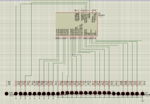
this is my circuit
i've tried it on a bread board with 15 led and it worked well with low delay
but when i used pcb with 29 led and the internal pull up resistors disabled, the led's are connected as shown in figure,
the code is as follows:
Code:
Define osc 20  'define 20 mhz crystal     
TRISB = 0  'define portb as output 
TRISC = 0
TRISD = 0
TRISA = 0

PORTB = 0  
PORTC = 0
PORTD = 0
PORTA = 0

COL VAR BYTE
CHAR0 VAR BYTE
CHAR1 VAR BYTE


CHAR2 VAR BYTE  'define variable with 1 byte size 
CHAR3 VAR BYTE


MAIN :   'label 
    
    FOR COL = 0 TO 63   'loop 
        
        LOOKUP COL, [ $08, $40, $20, $87, $38, $18, $18, $38,_   'use array to simplify dealing with items and send them to ports    
$78, $78, $F8, $FA, $FC, $4F, $FE, $CE,_
 $4C, $CC, $E9, $EB, $83, $C2, $1E, $1E,_
$3E, $0E, $0F, $06, $09, $10, $40, $60,_
$90, $FA, $98, $CA, $F0, $F8, $60, $F8,_
$7D, $F8, $FA, $FC, $F8, $F0, $F8, $FC,_
$F8, $FC, $F8, $FC, $F8, $FC, $F8, $D0,_
            $58, $30, $18, $F0, $18, $08, $08, $00],CHAR0

        LOOKUP COL, [ $00, $00, $00, $01, $20, $00, $00, $00, _    
$00, $00, $08, $03, $1F, $1F, $27, $C7,_
$66, $8F, $83, $80, $00, $80, $00, $00,_
$00, $00, $00, $00, $10, $F8, $FF, $FD,_
$FD, $F9, $F8, $FB, $F3, $F2, $EE, $CF,_
$28, $3F, $0F, $0F, $1F, $FF, $3F, $1F,_
$FF, $3F, $FF, $1F, $0F, $61, $07, $09,_
         $07, $00, $00, $80, $00, $00, $00, $00],CHAR1

        LOOKUP COL, [ $00, $00, $04, $00, $00, $00, $00, $00,_      
$00, $00, $00, $00, $00, $00, $00, $00,   _
$00, $01, $07, $FF, $FF, $FF, $7E, $3E,   _
$7C, $07, $00, $00, $00, $00, $00, $01,   _
$00, $13, $8F, $FF, $FF, $3F, $3F, $01,   _
$71, $04, $00, $00, $00, $00, $00, $00,   _
$02, $03, $08, $03, $E1, $F2, $FA, $A8,   _
          $A6, $E4, $C0, $00, $00, $00, $08, $00],CHAR2


  LOOKUP COL, [ $00, $00, $00, $00, $00, $00, $00, $00, _     
$00, $00, $00, $00, $00, $00, $00, $00, _
$00, $00, $00, $07, $23, $31, $08, $00, _
$00, $00, $00, $00, $00, $00, $00, $00, _
$00, $00, $00, $00, $01, $00, $00, $00, _
$00, $00, $00, $00, $00, $00, $00, $00, _
$00, $00, $00, $00, $00, $00, $00, $00, _
           $01, $07, $00, $00, $08, $04, $01, $00],CHAR3
        
        PORTB = CHAR0  'assign the value of char0 to portb
        PORTC = CHAR1
        
        PORTD = CHAR2
        PORTA = CHAR3
        
        Pauseus 1805  ' 120 / 63
        
    NEXT COL     ' increase index 
    
    
GOTO MAIN

END

i don't know about the capacitors ?! could u explain more ? and the switching current thing ?! shouldn't each pin gives 25Ma & 5 volt as output ?
u seems to know a lot about these things so plz could u give me additional information ?!
i don't play roughly on wires, it's (the led normal light) just keeps coming and going
 

P.S. i used 20MHZ Crystal with 2*33pF capacitors connected to the crystal and the ground
 

Thanks for the info.

Right...

1. The maximum total current of ports A, B and E combined is 200mA. Likewise, the maximum total current on ports C and D combined is 200mA. So, you can only have eight LED's on each of the two combined sets lit at any one time. More than that and you are exceeding the maximum allowable current. I don't know what happens to the PIC in that case, but it won't be good. (source: PIC microcontrollers, By Lucio Di Jasio, et al)

2. Capacitors... you need a 100nF capacitor between each pair of VDD/VSS pins, close to the chip. Also, because you are switching relatively high currents, you need extra capacitance to prevent the voltage suddenly sagging when a lot of LED's get switched on. For this, say a 470uF capacitor across the power rails. I might be tempted to say, for the same reason, an extra 10uF (preferably tantalum) across each pair of power pins in parallel with the 100nF ones. But then, you should not be switching this much current through the PIC anyway.

3. Make sure you have connected both pairs of power pins on the PIC to your power supply. You don't show that on the diagram if you have.

4. I've not looked at your code yet because the total current is possibly your problem right away.

Edit to add:

To get around the current issue you either need to use transistor switches on each LED, a few high-current buffer chips, or use low current (2mA) LED's.

You will find this sort of thing is a common issue. While each pin alone might be capable of a certain current, it does not necessarily follow that you can have that current through all the pins of a device simultaneously.

---------- Post added at 20:50 ---------- Previous post was at 20:38 ----------

I've just realised that the current situation is even worse:

The maximum current for the whole chip is 250mA into Vdd, or 300mA out of Vss.

Since your LED's are grounded, that means it is the current into Vdd that goes to them, so the 250mA maximum applies.
 
Last edited:

View attachment 69457
i've tried it on a bread board with 15 led and it worked well with low delay
but when i used pcb with 29 led and the internal pull up resistors disabled, the led's are connected as shown in figure,


i don't know about the capacitors ?! could u explain more ?

Are you referring to bypass or decoupling capacitors? It isn't clear as to which capacitors you are referring?


and the switching current thing ?! shouldn't each pin gives 25Ma & 5 volt as output ?

Reference: PIC16F87XA Datasheet, Section: 17.0 ELECTRICAL CHARACTERISTICS, Pg. 173

17.0 ELECTRICAL CHARACTERISTICS

Absolute Maximum Ratings †
Ambient temperature under bias............................................................................................. -55 to +125°C
Storage temperature ........................................................................................................... -65°C to +150°C
Voltage on any pin with respect to VSS (except VDD, MCLR. and RA4) ......................................... -0.3V to (VDD + 0.3V)
Voltage on VDD with respect to VSS ...................................................................................... -0.3 to +7.5V
Voltage on MCLR with respect to VSS (Note 2) .......................................................................... 0 to +14V
Voltage on RA4 with respect to Vss ......................................................................................... 0 to +8.5V
Total power dissipation (Note 1) .............................................................................................. 1.0W
Maximum current out of VSS pin .............................................................................................. 300 mA
Maximum current into VDD pin ................................................................................................. 250 mA
Input clamp current, IIK (VI < 0 or VI > VDD)........................................................................... ± 20 mA
Output clamp current, IOK (VO < 0 or VO > VDD) ..................................................................... ± 20 mA
Maximum output current sunk by any I/O pin............................................................................... 25 mA
Maximum output current sourced by any I/O pin .......................................................................... 25 mA
Maximum current sunk by PORTA, PORTB and PORTE (combined) (Note 3).......................................... 200 mA
Maximum current sourced by PORTA, PORTB and PORTE (combined) (Note 3)...................................... 200 mA
Maximum current sunk by PORTC and PORTD (combined) (Note 3) .................................................... 200 mA
Maximum current sourced by PORTC and PORTD (combined) (Note 3) ................................................ 200 mA


Note 1: Power dissipation is calculated as follows: Pdis = VDD x {IDD - Σ IOH} + Σ {(VDD - VOH) x IOH} + Σ(VOl x IOL)
2: Voltage spikes below VSS at the MCLR pin, inducing currents greater than 80 mA, may cause latch-up.
Thus, a series resistor of 50-100Ω should be used when applying a “low” level to the MCLR pin rather than
pulling this pin directly to VSS.
3: PORTD and PORTE are not implemented on PIC16F873A/876A devices


There are several current limiting specifications, however notice the device, PIC16F877A, is limited by how much current it can sink or source total.

Maximum current out of VSS pin .............................................................................................. 300 mA
Maximum current into VDD pin ................................................................................................. 250 mA

It is going to be difficult to drive 30 LEDs simultaneously from a single PIC. You may want to consider utilizing an LED driver device or port expander to drive the LEDs directly.


i don't play roughly on wires, it's (the led normal light) just keeps coming and going

The high current requirements maybe the cause of several anomalies, including voltage drop and device reset.


BigDog
 

Thanks a lot for ur help, i thought sth wrong with the current but i couldn't find any source to help me with such thing so thanks again,
the thing is that i found this video of the same project
Led Globus Maturski rad / Led Globe project - YouTube
as u can see the pcb has only pins for wires he didn't even use resistors and even though he uses big led's nd pic16f877 it works well ! i contacted him nd he said that he didn't use any resistor, won't that damage the led's ?!

about my problem could i connect each led directly to the +5v source with 1 ampere with 220ohm resistor between, and connect the cathode of each led to the pic and reverse the code so instead of sending 1's i send 0's ?!
i know it will consume more wires and be shagy but isn't it more flexible than exceeding the pcb size with transistors ?!

---------- Post added at 23:10 ---------- Previous post was at 23:07 ----------

Are you referring to bypass or decoupling capacitors? It isn't clear as to which capacitors you are referring?


Reference: PIC16F87XA Datasheet, Section: 17.0 ELECTRICAL CHARACTERISTICS, Pg. 173


There are several current limiting specifications, however notice the device, PIC16F877A, is limited by how much current it can sink or source total.


It is going to be difficult to drive 30 LEDs simultaneously from a single PIC. You may want to consider utilizing an LED driver device or port expander to drive the LEDs directly.


The high current requirements maybe the cause of several anomalies, including voltage drop and device reset.


BigDog

everything is clear now but i want to ask what is the difference between bypass or decoupling capacitors ?!
could u show me simple schematic for both ?! i've never connected capacitors with power rails and it was working well till this project
 

Always keep a copy of the devices datasheet handy:

PIC16F87XA Datasheet

As well as any available errata:

PIC16F877A Product Page


BigDog

i'll thanks :D

"everything is clear now but i want to ask what is the difference between bypass or decoupling capacitors ?!
could u show me simple schematic for both ?! i've never connected capacitors with power rails and it was working well till this project"
 

everything is clear now but i want to ask what is the difference between bypass or decoupling capacitors ?!
could u show me simple schematic for both ?! i've never connected capacitors with power rails and it was working well till this project

If effect bypass or decoupling capacitors form a low pass filter, bypassing any high frequency noise or EMI to Ground.

The typical PIC circuit utilizes a 0.1uF (100nF) capacitor between Vdd and Vss as close to the PIC as possible.

Here are a some reference material concerning bypass and decoupling capacitors:


ESR and Bypass Capacitor Self Resonant Behavior How to Select Bypass Caps

Decoupling

Bypass Capacitors: An Interview With Todd Hubing

Choosing and Using Bypass Capacitors

BigDog

---------- Post added at 22:35 ---------- Previous post was at 22:25 ----------

Here are a few more PIC related links:

Web platform hardware design - Interesting article with section dealing with bypass capacitors

PIC Proper Bypass Techniques

BigDog
 

what about this video ?
i found this video of the same project
Led Globus Maturski rad / Led Globe project - YouTube
as u can see the pcb has only pins for wires he didn't even use resistors and even though he uses big led's nd pic16f877 it works well ! i contacted him nd he said that he didn't use any resistor, won't that damage the led's ?!
 

The edaboard database had to be restored after quite a few extra questions and answers here, so I'm going to summarise what I said in them all from my memory.

I've no idea how the youtube project works without melting something. If the LED's really are standard LED's, with no resistors and a 5V supply, then both the PIC and the LED's should be molten junk. :shock: Personally, I think there is something we aren't being told about it.

...

With regards to current:

The same quantity of current must flow through every part of a circuit path, unless it comes to a junction where it can split or combine. In that case, you get the sum of the currents at that point. It does not matter which way the current is flowing, it must always be the same. Like water through a pipe - if a litre per minute is flowing through a pipe, the same rate must flow through all of that pipe. If it goes through a junction, it must still be flowing somewhere, in addition to anything else flowing in the subsequent parts from that juncction.

So, if you connect the LED cathode to ground (with its resistor) and the LED anode to a PIC pin, and turn on the PIC pin (set it high):

Conventional current can now flow from the +5V supply, through the PIC's power pins, through the PIC's internal connections to the i/o pin's ouput transistor, through the output pin which is now said to be sourcing that current, through the LED and resistor and finally to ground.

If the LED/resistor combination take 25mA at 5V, then that 25mA will flow through the PIC's i/o pin, and through the PIC itself in addition to whatever esle is already flowing through the PIC's power pins.


If the LED's cathode is connected to the PIC i/o pin, with its resistor, and the LED anode is connected to +5V, and the i/o pin set to zero:

Conventional current can flow from +5V supply, through the LED and resistor, into the PIC's i/o pin which is now said to be sinking that current, through the low-side pin output transistor into the PIC's internal connections, out through the PIC's ground power pin and evetually to circuit ground.

Again, if the LED/resistor combination draws 25mA, then that same 25mA will be flowing through the PIC's i/o pin, and be added to whatever is already flowing through its ground circuit and ground power pins.


Thus, 30 of these LED's, all lit, will each source or sink (depending which way you wire them) 25mA through its i/o pin, and the PIC itself will see an additional 30x25 = 750mA of current through either the +5V power pins or the ground power pins, again depending which way you have wired them. But in either direction, the PIC still has to have that 750mA flow through it. No way to avoid that without using more external components.


Hope that has made the current situation clearer.


Now, the ways around this are:

1. Use external current buffers of some description, including driver/buffer ic's or transistors.

2. Drop the LED current to around 9mA and use the PIC pins to sink current. That is, connect the LED anode to +5V and the cathode to the PIC. That way we can use the PIC's 300mA maximum sink (9mAx30 = 270mA, leaving a little bit of current for the PIC itself to use). A resistor of 360 ohm is probably a good value for an average red LED. This sill not be very bright with standard LED's - maybe switch to very high brightness types to offset the effect of the lower than optimum current.

3. Use low power LED's (generally around 2-3mA), running them at full current with an appropriate resistor. I guess around 1.2K would be correct for an average low-current red LED.

...

I just remebered another point that was made about current:

Components are not given a current as such. They are given a potential difference, or voltage, across them and that causes or allows a current to flow that depends on the characteristics of the component.

The PIC does not get involved in how much current flows into or out of its output pins, other than acting merely as a switch which connects the pin to either Vdd or Vss (or some other way on some of the pins, but the principles still apply).

It will not control the current, even if it is more than the PIC pin's transistors can handle, or more than the entire PIC itself can handle. Allow too much current and the PIC will be damaged.
 
Last edited:
The edaboard database had to be restored after quite a few extra questions and answers here, so I'm going to summarise what I said in them all from my memory.

I've no idea how the youtube project works without melting something. If the LED's really are standard LED's, with no resistors and a 5V supply, then both the PIC and the LED's should be molten junk. :shock: Personally, I think there is something we aren't being told about it.

...

With regards to current:

The same quantity of current must flow through every part of a circuit path, unless it comes to a junction where it can split or combine. In that case, you get the sum of the currents at that point. It does not matter which way the current is flowing, it must always be the same. Like water through a pipe - if a litre per minute is flowing through a pipe, the same rate must flow through all of that pipe. If it goes through a junction, it must still be flowing somewhere, in addition to anything else flowing in the subsequent parts from that juncction.

So, if you connect the LED cathode to ground (with its resistor) and the LED anode to a PIC pin, and turn on the PIC pin (set it high):

Conventional current can now flow from the +5V supply, through the PIC's power pins, through the PIC's internal connections to the i/o pin's ouput transistor, through the output pin which is now said to be sourcing that current, through the LED and resistor and finally to ground.

If the LED/resistor combination take 25mA at 5V, then that 25mA will flow through the PIC's i/o pin, and through the PIC itself in addition to whatever esle is already flowing through the PIC's power pins.


If the LED's cathode is connected to the PIC i/o pin, with its resistor, and the LED anode is connected to +5V, and the i/o pin set to zero:

Conventional current can flow from +5V supply, through the LED and resistor, into the PIC's i/o pin which is now said to be sinking that current, through the low-side pin output transistor into the PIC's internal connections, out through the PIC's ground power pin and evetually to circuit ground.

Again, if the LED/resistor combination draws 25mA, then that same 25mA will be flowing through the PIC's i/o pin, and be added to whatever is already flowing through its ground circuit and ground power pins.


Thus, 30 of these LED's, all lit, will each source or sink (depending which way you wire them) 25mA through its i/o pin, and the PIC itself will see an additional 30x25 = 750mA of current through either the +5V power pins or the ground power pins, again depending which way you have wired them. But in either direction, the PIC still has to have that 750mA flow through it. No way to avoid that without using more external components.


Hope that has made the current situation clearer.


Now, the ways around this are:

1. Use external current buffers of some description, including driver/buffer ic's or transistors.

2. Drop the LED current to around 9mA and use the PIC pins to sink current. That is, connect the LED anode to +5V and the cathode to the PIC. That way we can use the PIC's 300mA maximum sink (9mAx30 = 270mA, leaving a little bit of current for the PIC itself to use). A resistor of 360 ohm is probably a good value for an average red LED. This sill not be very bright with standard LED's - maybe switch to very high brightness types to offset the effect of the lower than optimum current.

3. Use low power LED's (generally around 2-3mA), running them at full current with an appropriate resistor. I guess around 1.2K would be correct for an average low-current red LED.

...

I just remebered another point that was made about current:

Components are not given a current as such. They are given a potential difference, or voltage, across them and that causes or allows a current to flow that depends on the characteristics of the component.

The PIC does not get involved in how much current flows into or out of its output pins, other than acting merely as a switch which connects the pin to either Vdd or Vss (or some other way on some of the pins, but the principles still apply).

It will not control the current, even if it is more than the PIC pin's transistors can handle, or more than the entire PIC itself can handle. Allow too much current and the PIC will be damaged.

Thank u very much, everything is now clear as crystal :d
but to make sure that i understand all of it correctly
if a device has components that consumes .5 ampere and i have 5 volt source with 1 ampere as an input there shouldn't be a problem since the device with take only .5 ampere and nothing will melt down ?
isn't that the case ? or it depends on how much the pin can handle ?
the final question here what cause the device to damage/meltdown (high volt or high current)? and depending on what ?
 

if a device has components that consumes .5 ampere and i have 5 volt source with 1 ampere as an input there shouldn't be a problem since the device with take only .5 ampere and nothing will melt down ?

That's correct. Forget about the PIC for a moment, just think about a power supply (PSU), an LED and a resistor.

A PSU gives a specific voltage, and can provide up to a certain amount of current depending on its design. If a 5V PSU rated at 40A (I have one on my shelf) is connected to one of your LED's with a 120 ohm resistor in series, then the PSU will provide its 5V to the LED/resistor and about 25mA current will be drawn by the LED/resistor. Nothing more. The ampere rating of the PSU is the maximum that can safely supply without damage to itself; it is not 'pushed' into things unless they 'ask' for it.


isn't that the case ? or it depends on how much the pin can handle ?

OK, back to the PIC. Remember, the PIC's pin when used as an output is just a switch. It uses transistors to connect the pin either to the + supply line, or the ground line. That's all it does. Think of it like that - a real double-throw toggle switch, with one side connected to +V, the other side connected to Ground, and the middle, switched contact as the ouput. Toggle one way and the output is positive, toggle the other and the output is ground.

Then, whatever you connect to that output, will draw whatever current it wants from the supply. But, that currrent must still flow through the switch, either from +V or to ground. So, if your switch only has a cthickness of cunductor that can handle 5A, then if your circuit draws 10A, the switch contacts will melt.

Each pin on the PIC can handle 25mA without being damaged - this is because it has tiny transistors inside. All of them are connected internally to the power rails. These internal power rails are also quite thin, so can only handle 250mA for the + rail, and 300mA for the ground rail (it's possibly a bit thicker). Also, there are probably seperate power rails for the ports, just like you might make on a PCB as you route around components. Thus the 200mA limits on the port groups.

the final question here what cause the device to damage/meltdown (high volt or high current)? and depending on what ?

In the case we are discussing, the potential damage is caused by excess current. Current is the movement of electrons in the conductors. Movement causes friction. Friction energy is dissipated as heat energy. Things can only get so hot before they suffer damage and, eventually, actually melt. The smaller a conductor is, the less energy it takes to make it too hot, thus the less current it can safely handle.

Too high a voltage can also cause damage, in two basic ways. First, more voltage often means that more current will be drawn. Think Ohm's law: Put a 100 ohm resistor across a 5V PSU, and 50mA will be drawn. If you increase the voltage to 50V, then Ohm's law says that 500mA will now be drawn. Put the same resistor across the mains (for me that's 230Vrms) and 2.3A will be drawn. If that resistor is just a little one normally used, like your LED resistors, 2.3A will make it fail in a nice, bright flash as it suddenly glows red hot and melts!

Also, too high a voltage can make devices fail because the voltage is able to jump across small gaps, including resistance layers in semconductors. This them makes a current flow, so really it's still current that does the damage, but the initial mechanism is a little different. Think lightening: the high voltage can jump from the cloud to the ground by causing air ionisation, but it's the current that then flows that melts the building wiring that it hits.

---------- Post added at 14:11 ---------- Previous post was at 13:55 ----------

Can I suggest something for you to read? It talks about transistors first, but a link at the bottom goes on to talk about voltage and current in resistors. The article gives a very good explanation of transistors, voltage and current, and dispells some myths that are held even by very experienced engineers.

SCIENCE HOBBYIST: how transistor works, an alternate viewpoint

This link is thanks to member LvW who posted it in another thread. It really is worth reading.
 
well, thanks again for the explanation, very helpful.
if it is as what u say,300ma for the -ve rails nd 300ma +ve 250ma
with 30led*25ma connected in my schematic this will surely exceed the maximum current that the thickness power rails and transistors inside pic can handle so when i set all of the pins to high then the led+ transistor circuitry should have draw 25ma for each and cause the pic to melt down but that wasn't the case, the pic just show random behavior. is it related to the fact that pic takes only 250ma from the main source so it won't be able to give what leds+resistors want (750ma) so no damage happens ?
--
i think the damage will happens for sure when i connect the cathode directly to resistor and +5v power rails and send 0's from pic cause in this case each 25ma will go to pic as 750ma as a whole which the pic can't handle and in this case melt down ?? hope that was true :d
 

is it related to the fact that pic takes only 250ma from the main source so it won't be able to give what leds+resistors want (750ma) so no damage happens ?
--
i think the damage will happens for sure when i connect the cathode directly to resistor and +5v power rails and send 0's from pic cause in this case each 25ma will go to pic as 750ma as a whole which the pic can't handle and in this case melt down ?? hope that was true :d


If the LED/resistors want to draw 750mA total (which, all on, they will) then that 750mA will flow through the PIC, to either power or ground depending which way you have them. Either way it is still 750mA through the PIC and will damage the PIC. The PIC cannot deliberately limit the current, it does not have the capability to do so. The 250mA mentioned is simply the maximum that can be allowed through the PIC without it starting to melt. Your circuit is entirely responsible for the current drawn. Don't forget that the PIC's own operating current needs to be included in the amount flowing through it; that's about 6.5mA into V+ and out to Ground. Add that to whatever current your circuit causes through the PIC.

At this point, we don;t really know if the code is faulty, if the wiring is faulty, or if the PIC was damaged by too much current. That damage could have been caused instantly that too many LED's were switched on, so it was instantly faulty. Or, you might have been lucky, not damaged the PIC, and the problem lies elsewhere.

Before continuing with anything though, you need to sort out the current issue because it will be an issue even if it wasn't at first. It will eventually damage the PIC.
 

meaning that damage suppose to happen in both case sinking or sourcing ?!
if i connect 360 ohm resistor instead of 220 ohm this will limit the current drawn from pic and i'll be able to light 30 led with low brightness light and a void the use of extra components
but since i'm using sourcing not sinking in my pcb should i replace 220ohm with higher resistor than 360 to reduce the total current drawing to about 230ma ?
 

Yes - you are getting there. Sourcing or sinking, the PIC still has the current flow through it.

360 ohms will give about 9mA with an average red LED, assuming the LED drops 1.8V. So, 30 of them will draw 270mA. That should just be safe if you connect them with the PIC sinking current (LED's and resistors between PIC pin and +5V) because the PIC can tolerate up to total 300mA when sinking current.

If you want to connect the LED's so the PIC sources current, then you have the 250mA sourcing limit - call it 240mA to allow 10mA for the PIC itself. So, 240mA/30 = 8mA, (5V-1.8V)/8mA = 400 ohm. You need to use 400 ohm resistors if you want to connect the PIC to source current.

Really, both the above currents are too high for comfort. It is poor practice to run things near their maximum ratings. Things like a slight over-voltage from your power supply due to mains fluctuations, tolerences in the resistors giving values that are a bit low, even the room being warm can cause problems if you are already at the maximum. Personally I would drop the current by a further 10% (at least) to give a safety margin. That means changing the 360 ohm resistors to 400 ohm for the PIC-sinking circuit, or the 400 ohm for at least 440 ohm on the PIC-sourcing circuit.
 
thanks a lot for everything, i learned a lot of new things from u, so thanks a gain, u'r efforts are appreciated,
everything is clear now more that ever :d
 

Yes - you are getting there. Sourcing or sinking, the PIC still has the current flow through it.

360 ohms will give about 9mA with an average red LED, assuming the LED drops 1.8V. So, 30 of them will draw 270mA. That should just be safe if you connect them with the PIC sinking current (LED's and resistors between PIC pin and +5V) because the PIC can tolerate up to total 300mA when sinking current.

If you want to connect the LED's so the PIC sources current, then you have the 250mA sourcing limit - call it 240mA to allow 10mA for the PIC itself. So, 240mA/30 = 8mA, (5V-1.8V)/8mA = 400 ohm. You need to use 400 ohm resistors if you want to connect the PIC to source current.

Really, both the above currents are too high for comfort. It is poor practice to run things near their maximum ratings. Things like a slight over-voltage from your power supply due to mains fluctuations, tolerences in the resistors giving values that are a bit low, even the room being warm can cause problems if you are already at the maximum. Personally I would drop the current by a further 10% (at least) to give a safety margin. That means changing the 360 ohm resistors to 400 ohm for the PIC-sinking circuit, or the 400 ohm for at least 440 ohm on the PIC-sourcing circuit.

one more question
can i use the uln2803 to light the 30 led 8 for each
from what i know this ic apply sinking not sourcing to all led's
as in the figure below
so is that true ? can i use it to source instead of sink ?!
**broken link removed**
 

Status
Not open for further replies.

Similar threads

Part and Inventory Search

Welcome to EDABoard.com

Sponsor

Back
Top