davidwuf
Junior Member level 1
Hi all:
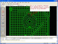
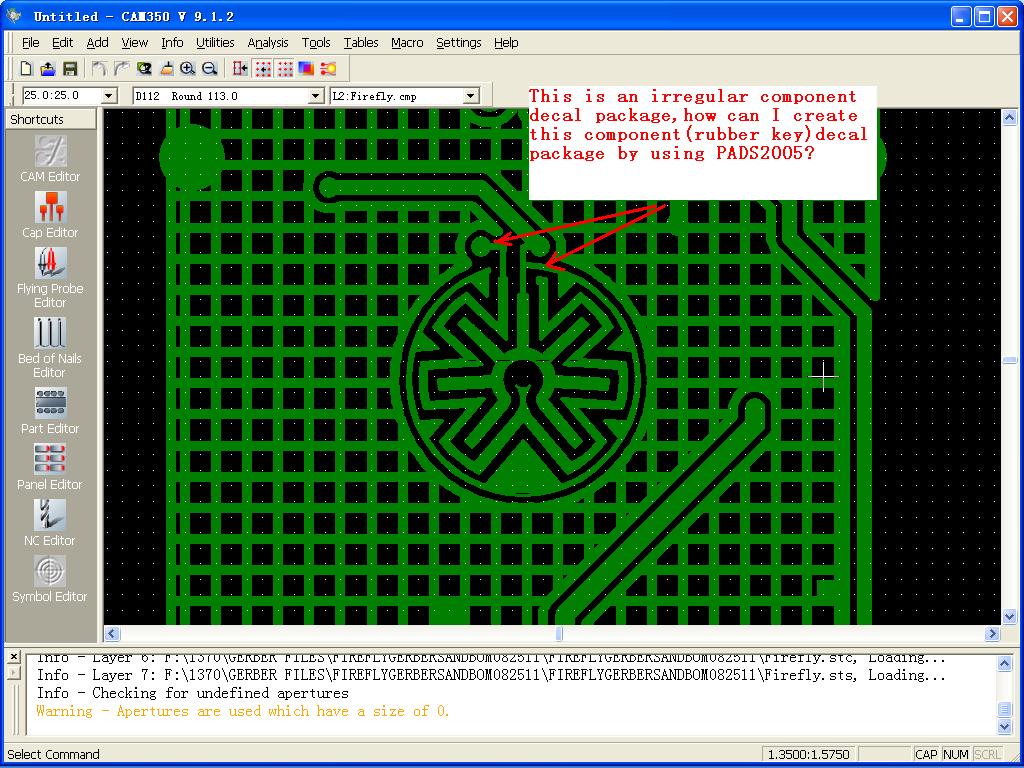
How can I create a irregular component footprint using PADS2005?
As the attached picture shown. for the rubber key, how to create its footprint?
Thank you,
David Wuf
---------- Post added at 10:46 ---------- Previous post was at 10:42 ----------
Add image link:
https://obrazki.elektroda.pl/17_1321926261.jpg
")